Where to Find a Heat Exchanger Thermal Design Calculations Spreadsheet
For a double pipe heat exchanger thermal design calculations spreadsheet, click here to visit our spreadsheet store. Read on for information about the use of a heat exchanger design thermal design calculations spreadsheet for a double pipe heat exchanger.
The Basic Equation for a Heat Exchanger Thermal Design Calculations Spreadsheet
The basic heat exchanger design equation is: Q = U A ΔTlm, where:
- Q = the rate of heat transfer between the two fluids in the heat exchanger in But/hr (kJ/hr for S.I. units)
- U is the overall heat transfer coefficient in Btu/hr-ft2–oF (kJ/hr-m2-K for S.I. units)
- A is the heat transfer surface area in ft2 (m2 for S.I. units)
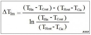
- ΔTlm is the log mean temperature difference in oF, (K for S.I units) calculated from the inlet and outlet temperatures of both fluids.
For a heat exchanger thermal design calculations spreadsheet, the heat exchanger equation can be used to calculate the required heat exchanger area for known or estimated values of the other three parameters, Q, U, and ΔTlm. Each of those parameters will be discussed briefly in the next three sections.
The Log Mean Temperature Difference, ΔTlm , for a Heat Exchanger Design Spreadsheet
 The driving force for a heat transfer process is always a temperature difference. For heat exchangers, there are always two fluids involved, and the temperatures of both are changing as they pass through the heat exchanger. Thus some type of average temperature difference is needed. Many heat transfer textbooks (e.g. ref #1 below) show
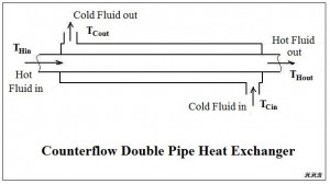
  that the log mean temperature difference is the appropriate average temperature difference to use for heat exchanger design calculations. The definition of the log mean temperature difference is shown in the figure above. The meanings of the four temperatures in the log mean temperature difference equation are rather self explanatory as shown in the diagram of a counterflow double pipe heat exchanger at the right.
The Heat Transfer Rate, Q, for a Heat Exchanger Thermal Design Calculations Spreadsheet
In order to use the heat exchanger design equation to calculate a required heat transfer area, a value is needed for the heat transfer rate, Q. This rate of heat flow can be calculated if the flow rate of one of the fluids is known along with its specific heat and the required temperature change for that fluid. The equation to be used is shown below for both the hot fluid and the cold fluid:
Q = mH CpH (THin – THout) = mC CpC (TCout – TCin), where
- mH is the mass flow rate of the hot fluid in slugs/hr (kg/hr for S.I. units).
- CpH is the specific heat of the hot fluid in Btu/slug-oF (kJ/kg-K for S.I. units).
- mC is the mass flow rate of cold fluid in slugs/hr (kg/hr for S.I. units).
- CpC is the specific heat of the cold fluid in Btu/slug-oF (kJ/kg-K for S.I. units).
- The temperatures (THin, THout, TCout, & TCin) are the hot and cold fluid temperatures going in and out of the heat exchanger, as shown in the diagram above. They should be in oF for U.S. or K for S.I. units.
The heat transfer rate, Q, can be calculated in a preliminary heat exchanger design spreadsheet if the flow rate, heat capacity and temperature change are known for either the hot fluid or the cold fluid. Then one unknown parameter can be calculated for the other fluid. (e.g. the flow rate, the inlet temperature, or the outlet temperature.)
The Overall Heat Transfer Coefficient, U, for a Heat Exchanger Design Spreadsheet
The overall heat transfer coefficient, U, depends on the convection coefficient inside the pipe or tube, the convection coefficient on the outside of the pipe or tube, and the thermal conductivity of the pipe wall. See the article, Forced Convection Heat Transfer Coefficient Calculations, for information about calculating the heat transfer coefficients and click here to visit our spreadsheet store, for spreadsheets to calculate the inside and outside convection coefficients and to calculate the overall heat transfer coefficient.
A Heat Exchanger Thermal Design Calculations Spreadsheet
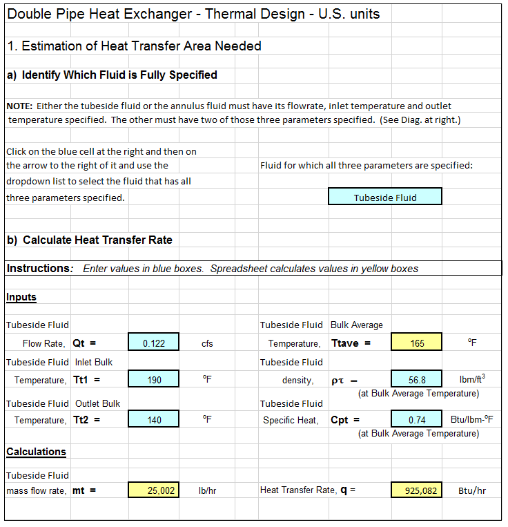
The screenshot below shows a heat exchanger thermal design calculations spreadsheet that can be used to carry out thermal design of a double pipe heat exchanger. The image shows only the beginning of the calculations. The rest of the spreadsheet will calculate the length of pipe needed, the length of each pass for a selected number of 180 degree bends, and the pressure drop through the inside of the pipe. Why bother to make these calculations by hand? This Excel spreadsheet is available in either U.S. or S.I. units at a very low cost at in our spreadsheet store.
References
1. Kuppan, T., Heat Exchanger Design Handbook, CRC Press, 2000.
2. Kakac, S. and Liu, H., Heat Exchangers: Selection, Rating and Thermal Design, CRC Press, 2002.
3. Bengtson, H., Fundamentals of Heat Exchangers, an online, continuing education course for PDH credit.
4. Bengtson, H., Thermal Design of a Double Pipe Heat Exchanger, and online blog article.

