MBBR Nitrification Denitrification Spreadsheet

Where to Find an MBBR Nitrification  Denitrification Spreadsheet

To obtain an MBBR Nitrification Denitrification spreadsheetclick here to visit our spreadsheet store.  This Excel spreadsheet is intended for MBBR nitrification denitrification process design calculations. You can buy a convenient MBBR Nitrification Denitrification spreadsheet  for a very reasonable price.  This spreadsheet makes MBBR process design calculations for BOD removal, nitrification, and denitrification. including both pre-anoxic and post-anoxic denitrification processes.  It is available in either U.S. units or S.I. units.  Read on for information about using an MBBR process design calculations spreadsheet for nitrification and denitrification.

Background for MBBR Nitrification Denitrification Spreadsheet

The moving bed biofilm reactor (MBBR) appeared relatively recently on the wastewater treatment scene.  It was developed in the 1990’s, and is now used in many countries around the world.

The MBBR wastewater treatment process is quite flexible.  It is used for domestic and industrial wastewater treatment and can be designed for BOD removal alone or in combination with nitrification or with nitrification and denitrification.  It is used as a single stage process or as a two-stage or three-stage process.

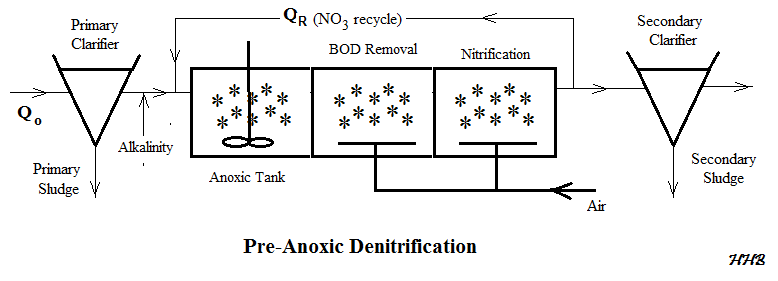
The diagram below shows the general configuration of a Pre-anoxic nitrification denitrification MBBR wastewater treatment process.  Denitrification can also be carried out in a Post-Anoxic nitrification denitrification process.

MBBR Nitrification Denitrification Spreadsheet flow diagram

MBBR Pre-Anoxic Nitrification Denitrification Flow Diagram

 Example MBBR Wastewater Treatment Design Spreadsheet

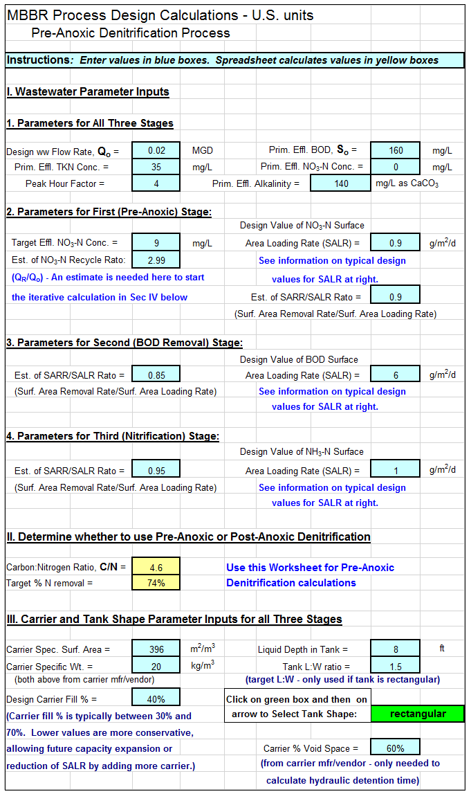
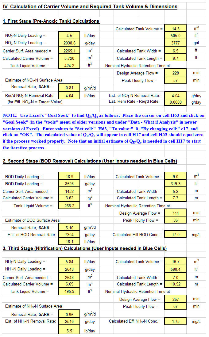
An example MBBR nitrification denitrification spreadsheet is partially shown in the two images below.  This Excel spreadsheet can be used to calculate the required MBBR tank volume and dimensions, based on user input media information and wastewater design flow and characteristics.  This Excel spreadsheet, as well as others for wastewater treatment process design calculations, is available in either U.S. or S.I. units for a very reasonable price in our spreadsheet store.

MBBR Nitrification Denitrification Spreadsheet Screenshot1

Screenshot1 – Pre-anoxic Nitrification Denitrification

MMBR Nitrification Denitrification Spreadsheet Screenshot2

Screenshot2 – Pre-anoxic MBBR Nitrification Denitrification Spreadsheet

 References:

1. McQuarrie, J.P. and Boltz, J.P., Moving Bed Bio-film Reactor Technology: Process Design and Performance, Water Environment Research, Vol 83, No 6, June 2011.

2. Bengtson, Harlan, “MBBR Denitrification Design Spreadsheet,” an online blog article

3. Bengtson, Harlan H., “Biological Wastewater Treatment Process Design Calculations,” available as an Amazon Kindle ebook or as a paperback.

4. Bengtson, Harlan H., “Spreadsheets for MBBR Denitrification Design Calculations,” an Amazon Kindle ebook.

5. Bengtson, Harlan H., “Spreadsheets for MBBR Process Design Calculations,”  available as an Amazon Kindle ebook or as a paperback.

Air Viscosity Temperature Calculator Spreadsheet

Where to Find an Air Viscosity Temperature Calculator Spreadsheet

To obtain an Air Viscosity Temperature Calculator excel spreadsheet, click here to visit our spreadsheet store.  Why use online calculators or tables to find the viscosity of air at a specified pressure and temperature when you can buy a convenient air viscosity temperature calculator excel spreadsheet for only $4.95?  This spreadsheet will calculate the viscosity of air at specified pressure and temperature in either U.S. or S.I. units.  Read on for information about Excel spreadsheets that can be used as an Air viscosity temperature calculator for specified pressure and temperature.

Air Viscosity Temperature Calculator Spreadsheet Applications

An  Air Viscosity Temperature calculator excel spreadsheet  can be used for any situation where a value of air viscosity is needed at a specified pressure and temperature.  This could include calculations for air flow in a pipe, drag force or drag coefficient calculations for flow of an object through air, and any other calculation requiring the Reynolds number for air flow or flow through air.  For example, see the related article, Fanno Flow Excel Spreadsheet for Air Flow in a Pipe.

Equations for an Air Viscosity Temperature Calculator Spreadsheet

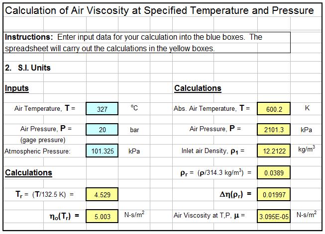
Equations are available for an air viscosity temperature calculator to calculate the viscosity of air at specified temperature and pressure.  The spreadsheet shown in  the diagram below calculates air density using an equation for air viscosity as a function of temperature ratio, Tr , and density ratio, ρr  , where in U.S. units:  Tr   =  T/238.5 with T in degrees R  and ρr    =  ρ/0.6096 with ρ in slugs/ft3.  Since the air density is needed for this calculation, the spreadsheet also calculates the density of air at the specified air temperature and pressure.  The complete equations are included in the spreadsheet discussed above and shown in the screenshot below.

Example Air Viscosity Temperature Calculator Excel Spreadsheet

The Air Viscosity Temperature calculator excel spreadsheet shown in the image below can be used to calculate the viscosity of air at given temperature and pressure as discussed above.  This Excel spreadsheet and others for fluid properties calculations, in either U.S. or S.I. units are available for very reasonable prices in our spreadsheet store.

Air Viscosity Temperature Calculator Spreadsheet

References

1. Bengtson, Harlan H, “Air Viscosity Calculator Pressure Temperature Spreadsheet,”  An online informational blog article.

Pipe Culvert Design Spreadsheet Calculations

Where to get a circular pipe culvert design spreadsheet

For pipe culvert design spreadsheets in either U.S. or S.I. units, click here to visit our spreadsheet store.  Obtain convenient, easy to use spreadsheets for culvert design calculations at reasonable prices. Read on for information about the use of Excel spreadsheets for circular culvert design.

Inlet Control and Outlet Control for a Pipe Culvert Design Spreadsheet

One of the general conditions for pipe culvert design calculations is inlet control, in which the flow rate through the culvert is controlled at the inlet end of the culvert by the culvert diameter and other inlet conditions.  The other general condition is outlet control, in which the flow rate is controlled by the outlet conditions and the entire length of the culvert.

Pipe Culvert Inlet Control Design Spreadsheet Calculations

An equation that relates culvert parameters for inlet control conditions in a pipe culvert design spreadsheet is:

Culvert Design Equation for Inlet Control Conditionswhere:

  • HW = headwater depth above inlet invert (ft – U.S. or m – S.I.)
  • D = inside height of the culvert (ft – U.S. or m – S.I.)
  • Q = discharge (cfs – U.S. or m3/s – S.I.)
  • A = cross-sectional area of culvert (ft2 – U.S. or m2 – S.I.)
  • S = culvert slope (dimensionless)
  • K1 = 1.0 for U.S. units or 1.811 for S.I. units
  • Ks = slope constant = -0.5 for a non-mitered or + 0.7 for a mitered inlet
  • Y and c are constants dependent on the type of culvert and type of inlet.

Pipe Culvert Outlet Control Design Calculations

An equation that relates culvert parameters for outlet control conditions in a pipe culvert design spreadsheet is:

Head Loss Equation for Outlet Control Culvert DesignWhere:

  • hL = the head loss in the culvert barrel for full pipe flow (ft – U.S. or m – S.I.)
  • Ku = 29 for U.S. units or 19.63 for S.I. units
  • n = Manning roughness coefficient for the culvert material
  • L = length of the culvert barrel (ft – U.S. or m – S.I.)
  • R = hydraulic radius of the full culvert barrel = A/P (ft – U.S. or m – S.I.)
  • A = cross-sectional area of the culvert barrel (ft2 – U.S. or m2 – S.I.)
  • P = perimeter of the culvert barrel, ft or m
  • V = velocity in the culvert barrel, ft/sec or m/s
  • Ke = loss coefficient for pipe entrance

A spreadsheet screenshot for pipe culvert design calculations


The Excel spreadsheet screenshot below shows part of a spreadsheet for circular culvert design calculations based on inlet control.   Based on the indicated input values, the spreadsheet will calculate the minimum required pipe culvert diameter and the headwater depth for the next larger standard culvert diameter.

For low cost, easy to use spreadsheets to make these calculations in S.I. or U.S. units, click here to visit our spreadsheet store.

screenshot for pipe culvert design spreadsheet

References

1.  Hydraulic Design of Highway Culverts,Third Edition,  Publication No. FHWA-HIF-12-026, U.S. DOT/Federal Highway Administration, April, 2012.

2. Bengtson, Harlan H., “Spreadsheets for Circular Culvert Design.”, an online article.

Hydraulic Jump Calculator Excel Spreadsheets

Where to Find Hydraulic Jump Calculator Excel Spreadsheets

For an Excel spreadsheets to use as an open channel flow, hydraulic jump calculatorclick here to visit our spreadsheet store.  Obtain a convenient, easy to use rectangular channel hydraulic jump calculator spreadsheet for only $14.95. Read on for information about the use of an Excel spreadsheet as a horizontal, rectangular channel hydraulic jump calculator.

Background for Hydraulic Jump Calculator

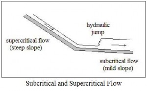
In order to discuss hydraulic jumps it’s necessary to talk about subcritical and supercritical flow.  In general subcritical flow takes place at low velocities and high flow depths, while supercritical flow occurs at high velocities and low flow depths.  For more details about critical, subcritical, and supercritical flow, see the article, “Open Channel Flow Spreadsheets – Critical Depth and Critical Slope.”  The diagram above shows supercritical flow on a steep slope, changing to subcritical flow on a mild slope.  As shown, the transition from supercritical flow to subcritical flow takes place with a hydraulic jump.  Whenever supercritical flow takes place on a slope that isn’t steep enough to maintain supercritical flow, the transition to subcritical flow will take place through the mechanism of a hydraulic jump as illustrated in the diagram.

Hydraulic Jump Calculator Parameters

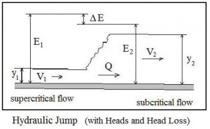
Hydraulic jump calculations center on relationships among the supercritical conditions before the jump (upstream or initial conditions) and the subcritical conditions after the jump (downstream or sequent conditions).  The diagram at the left shows initial supercritical parameters and sequent subcritical parameters for a hydraulic jump.  The parameters and their typical units are summarized below:

  • y1 = the initial (upstream) depth of flow in ft for U.S. or m for S.I. units
  • V1 = the initial (upstream) liquid velocity in ft/sec for U.S. or m/s for S.I. units
  • E1 = the initial (upstream) head in ft for U.S. or m for S.I. units
  • y2 = the sequent (downstream) depth of flow in ft for U.S. or m for S.I. units
  • V2 = the sequent (downstream) liquid velocity in ft/sec for U.S. or m/s for S.I. units
  • E2 = the sequent (downstream) head in ft for U.S. or m for S.I. units
  • Q = the flow rate through the hydraulic jump in cfs for U.S. or m3/s for S.I. units
  • ΔE = the head loss across the hydraulic jump in ft for U.S. or m for S.I. units

An Excel Spreadsheet as a Hydraulic Jump Calculator

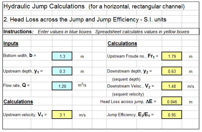
The Excel spreadsheet template shown below can be used to carry out hydraulic jump calculations.   Why bother to make these calculations by hand?  This Excel spreadsheet can calculate the sequent depth, sequent velocity, jump length, head loss across the jump, and hydraulic jump efficiency for specified initial depth, flow rate and channel width.  These spreadsheets are available in either U.S. or S.I. units at a very low cost (only $14.95 in our spreadsheet store.  These spreadsheets also have a tab for calculation of flow rate under a sluice gate and all of the equations used in the spreadsheet calculations are shown on the spreadsheets.

Note that some of the equations used in the spreadsheet calculations apply only for rectangular, horizontal channels, so the spreadsheets should be used only for channels that are at least approximately rectangular in cross-section and have a zero or very small slope.

References

1. Harlan H. Bengtson, “Hydraulic Jumps and Supercritical and Nonuniform Open Channel Flow,”  an online continuing education course for Professional Engineers.

2.  U.S. Department of Transportation, FHWA, Hydraulic Design of Energy Dissipators for Culverts and Channels, Hydraulic Engineering Circular No. 14, 3rd Ed, Chapter 6: Hydraulic Jump.

Activated Sludge Secondary Clarifier Design Spreadsheets

Where to Find Activated Sludge Secondary Clarifier Design Spreadsheets

For an Excel spreadsheet for activated sludge secondary clarifier design calculations, click here to visit our spreadsheet store.  Obtain a convenient, easy to use primary and secondary clarifier design spreadsheets for only $11.95.  Read on for information about the use of an Excel spreadsheet for activated sludge secondary clarifier design calculations.

Activated Sludge Secondary Clarifier Design Parameters

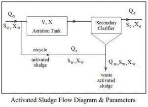
Flow Diagram for Activated Sludge Secondary Clarifier DesignThe parameters typically used for activated sludge secondary clarifier design are the surface overflow rate (SOR), solids loading rate (SLR), and weir overflow rate (WOR).  Activated sludge parameters are shown in the flow diagram at the right.  The equations defining these three parameters are:

SOR = Qo/A,  SLR = (Qo + Qr)X/A, and  WOR = Qo/L,  where:

  • Qo = primary effluent flow rate in MGD (U.S.) or m3/d (S.I.)
  • A = total surface area for secondary clarifier(s) in ft2 (U.S.) or m2 (S.I.)
  • Qr = recycle activated sludge flow rate in MGD (U.S.) or m3/d (S.I.)
  • X = mixed liquor activated sludge solids concentration in mg/L (U.S. or S.I.)
  • L = length of secondary clarifier effluent weir in ft (U.S.) or m (S.I.)

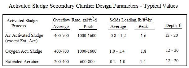
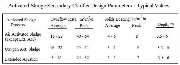
Typical values of surface overflow rate and solids overflow rate for activated sludge secondary clarifier design are shown in the tables below:

Design Parameters for Activated Sludge Secondary Clarifier Design

Activated Sludge Secondary Clarifier Design Parameters

Calculation of Activated Sludge Secondary Clarifier Surface Area

The equation for calculating the needed activated sludge secondary clarifier surface area from a design SOR value with units as shown above is:  A = Qo*106/SOR

The formula for calculating activated sludge secondary clarifier surface area from a design value of SLR with parameter units as shown above is:  A = (Qo + Qr)*8.34*X/SLR

An Excel Spreadsheet as an Activated Sludge Secondary Clarifier Design Calculator

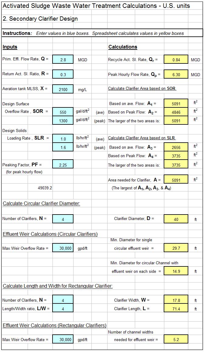
The Excel spreadsheet template shown below can be used to carry out the activated sludge secondary clarifier design calculations described above.   Why bother to make these calculations by hand?  This Excel spreadsheet can handle primary and secondary clarifier surface area calculations and determine diameter for circular clarifier(s) or length and width for rectangular clarifier(s) and is available in either U.S. or S.I. units at a very low cost (only $11.95)  in our spreadsheet store.  These spreadsheets also make weir overflow calculations to aid in effluent weir design.

screenshot of activated sludge secondary clarifier design spreadsheet

Reference

1. Metcalf & Eddy, Inc, (revised by Tchobanoglous, G, Burton, F.L., Stensel, H.D., Wastewater Engineering Treatment and Reuse, 4th Edition, New York, NY, 2003.


Storm Water Drain Inlet Calculations Spreadsheet

Introduction

For a storm water drain inlet calculations spreadsheet, click here to visit our spreadsheet store.  Read on for information about storm water inlet design and Excel spreadsheets to do the calculations.

Design of storm water drain inlets is basically determining the size opening needed to handle the design peak storm water runoff rate, for the particular type of inlet opening.  The links above also have spreadsheets for calculating the peak storm water runoff rate with the Rational Method equation.

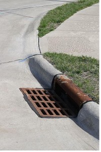
Types of Pavement Drain Inlets

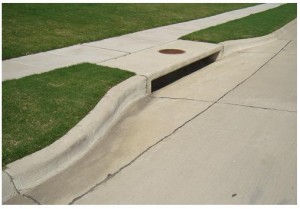
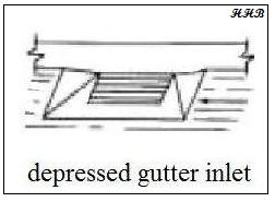
stormwater drain inlet calculations spreadsheet curb inlet figureThe types of pavement drain inlets in common use include curb inlets, gutter inlets and combination inlets.  A curb inlet is just an opening in the curb as shown in the image at the stormwater drain inlet calculations spreadsheet gutter inlet figureleft.  A combination inlet has both a curb opening and a grate opening in the bottom of the gutter as shown in the image at the right.  Gutter inlets typically have a grate over the opening, while curb inlets are storm water drain inlet calculations spreadsheet depressed gutter inlettypically open without a grate, as shown in the pictures.  A sketch of a depressed gutter inlet is shown at the bottom left.

Curb Inlet Image Credit: Lone Star Manhole and Structures

Combination Inlet Image Credit: Robert Lawton – Wikimedia Commons

Depressed Gutter Inlet Image Credit:  H. H. Bengtson

The Weir Model for Sizing Storm Water Drain Inlets

The openings for storm water drains can be modeled as a weir if the opening isn’t completely submerged at the design storm water runoff flow rate.  For a curb opening this would be the case if the depth of storm water at the opening is less than the height of the opening.  For a gutter opening it would occur if the design flow rate of storm water runoff enters the grate around the edges, without completely submerging the opening.

The equation used to size storm drains with unsubmerged openings is theC sharp crested weir equation:  Q = CwLd1.5, where:

  • Q = the design storm water runoff rate that must flow through the inlet in cfs for U.S. or m3/s for S.I. units.
  • Cw = a weir coefficient, which is a dimensionless constant.  Typical values are 2.3 for U.S. units and 1.27 for S.I. units.
  • L = the length of the curb opening (or the length of the the gutter opening in the direction of the storm water flow), in ft for U.S. or m for S.I. units.
  • d = the depth of storm water above the bottom of the curb opening or its depth above the gutter inlet opening in ft for U.S. or m for S.I. units.

The Orifice Model for Sizing Storm Water Drain Inlets

The storm water drain opening can be modeled as an orifice if it will be completely submerged at design flow of storm water runoff.  This would be the case for a curb opening if the water depth is more than the height of the curb opening at design storm water flow.  A gutter opening could be modeled as a weir if the gutter opening is completely submerged at the design storm water runoff rate.  The equation used for sizing storm water inlets with the orifice model is:

Q = Co A(2gde)1/2 ,  where:

  • Q = the design storm water runoff rate that must flow through the inlet in cfs for U.S. or m3/s for S.I. units.
  • Co = the orifice coefficient, which is dimensionless.  The value typically used for storm water inlet design is 0.67.
  • A = the area of the inlet opening in ft2 for U.S. or m2 for S.I. units.
  • g = the acceleration due to gravity (32.2 ft/sec2 for U.S. or 9.82 m/s2 for S.I units).
  • de = the height of storm water above the centroid of the opening in ft for U.S. or m for S.I. units.

Note that de = d – h/2, for a curb opening, where d is the depth of storm water above the bottom of the opening and h is the height of the curb opening.  For a gutter opening,  de = d, where d is the height of storm water above the gutter opening at design storm water flow.

An Excel Spreadsheet as a Storm Water Drain Inlet Design Calculator

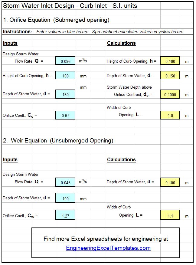
The Excel spreadsheet template shown below can be used to calculate the required size of a curb inlet for storm water drainage, based on specified information about the design storm water runoff rate, height of the curb opening, and the height of the storm water above the bottom of the opening.  Why bother to make these calculations by hand?  This Excel spreadsheet and others with similar calculations for a gutter opening are available in either U.S. or S.I. units at a very low cost in our spreadsheet store.

storm water inlet calculations spreadsheet

References:

1. McCuen, Richard H., Hydrologic Analysis and Design, 2nd Ed, Upper Saddle River, NJ, 1998.

2. ASCE. 1992. Design and Construction of Urban Stormwater Management Systems. The Urban Water Resources Research Council of the American Society of Civil Engineers (ASCE) and the Water Environment Federation. American Society of Civil Engineers, New York, NY.

3. Texas Department of Transportation/Online Hydraulic Design Manual/Storm Drain Inlets.


Heat Exchanger Thermal Design Calculations Spreadsheet

Where to Find a Heat Exchanger Thermal Design Calculations Spreadsheet

For a double pipe heat exchanger thermal design calculations spreadsheetclick here to visit our spreadsheet store.  Read on for information about the use of a heat exchanger design thermal design calculations spreadsheet for a double pipe heat exchanger.

The Basic Equation for a Heat Exchanger Thermal Design Calculations Spreadsheet

The basic heat exchanger design equation is:  Q = U A ΔTlm,    where:

  • Q = the rate of heat transfer between the two fluids in the heat exchanger in But/hr (kJ/hr for S.I. units)
  • U is the overall heat transfer coefficient in Btu/hr-ft2oF  (kJ/hr-m2-K for S.I. units)
  • A is the heat transfer surface area in ft2 (m2 for S.I. units)
  • ΔTlm is the log mean temperature difference in oF,  (K for S.I units)  calculated from the inlet and outlet temperatures of both fluids.

For a heat exchanger thermal design calculations spreadsheet, the heat exchanger equation can be used to calculate the required heat exchanger area for known or estimated values of the other three parameters, Q, U, and ΔTlm.  Each of those parameters will be discussed briefly in the next three sections.

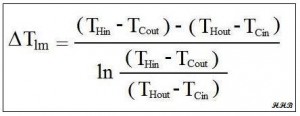
The Log Mean Temperature Difference, ΔTlm , for a Heat Exchanger Design Spreadsheet

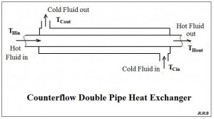
Equation for heat exchanger thermal design calculations spreadsheetThe driving force for a heat transfer process is always a temperature difference. For heat exchangers, there are always two fluids involved, and the temperatures of both are changing as they pass through the heat exchanger.  Thus some type of average temperature difference is needed.  Many heat transfer textbooks (e.g. ref #1 below) show double pipe heat exchanger diagram for heat exchanger thermal design calculations spreadsheetthat the log mean temperature difference is the appropriate average temperature difference to use for heat exchanger design calculations.  The definition of the log mean temperature difference is shown in the figure above.  The meanings of the four temperatures in the log mean temperature difference equation are rather self explanatory as shown in the diagram of a counterflow double pipe heat exchanger at the right.

The Heat Transfer Rate, Q, for a Heat Exchanger Thermal Design Calculations Spreadsheet

In order to use the heat exchanger design equation to calculate a required heat transfer area,  a value is needed for the heat transfer rate, Q.  This rate of heat flow can be calculated if the flow rate of one of the fluids is known along with its specific heat and the required temperature change for that fluid. The equation to be used is shown below for both the hot fluid and the cold fluid:

Q = mH CpH (THin – THout) = mC CpC (TCout – TCin), where

  • mH is the mass flow rate of the hot fluid in slugs/hr (kg/hr for S.I. units).
  • CpH is the specific heat of the hot fluid in Btu/slug-oF (kJ/kg-K for S.I. units).
  • mC is the mass flow rate of cold fluid in slugs/hr (kg/hr for S.I. units).
  • CpC is the specific heat of the cold fluid in Btu/slug-oF (kJ/kg-K for S.I. units).
  • The temperatures (THin, THout, TCout, & TCin) are the hot and cold fluid temperatures going in and out of the heat exchanger, as shown in the diagram above.  They should be in oF for U.S. or K for S.I. units.

The heat transfer rate, Q, can be calculated in a preliminary heat exchanger design spreadsheet if the flow rate, heat capacity and temperature change are known for either the hot fluid or the cold fluid. Then one unknown parameter can be calculated for the other fluid.  (e.g. the flow rate, the inlet temperature, or the outlet temperature.)

The Overall Heat Transfer Coefficient, U, for a Heat Exchanger Design Spreadsheet

The overall heat transfer coefficient, U, depends on the convection coefficient inside the pipe or tube, the convection coefficient on the outside of the pipe or tube, and the thermal conductivity of the pipe wall.  See the article, Forced Convection Heat Transfer Coefficient Calculations, for information about calculating the heat transfer coefficients and click here to visit our spreadsheet store, for spreadsheets to calculate the inside and outside convection coefficients and to calculate the overall heat transfer coefficient.

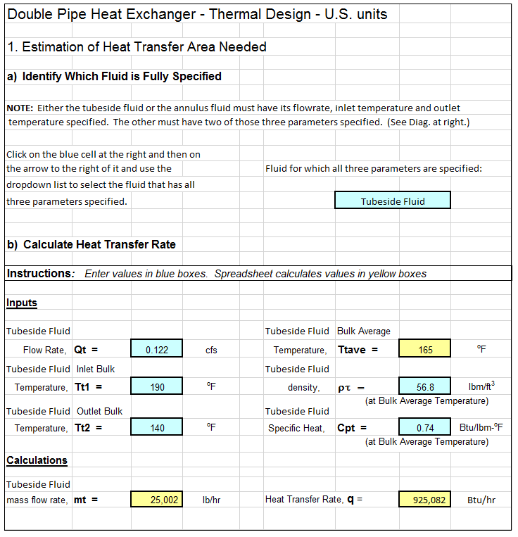
A Heat Exchanger Thermal Design Calculations Spreadsheet

The screenshot below shows a heat exchanger thermal design calculations spreadsheet that can be used to carry out thermal design of a double pipe heat exchanger.  The image shows only the beginning of the calculations.  The rest of the spreadsheet will calculate the length of pipe needed, the length of each pass for a selected number of 180 degree bends, and the pressure drop through the inside of the pipe.  Why bother to make these calculations by hand?  This Excel spreadsheet is available in either U.S. or S.I. units at a very low cost at in our spreadsheet store.

Heat Exchanger Thermal Design Calculations Spreadsheet

References

1. Kuppan, T., Heat Exchanger Design Handbook, CRC Press, 2000.

2. Kakac, S. and Liu, H., Heat Exchangers: Selection, Rating and Thermal Design, CRC Press, 2002.

3. Bengtson, H., Fundamentals of Heat Exchangers, an online, continuing education course for PDH credit.

4. Bengtson, H., Thermal Design of a Double Pipe Heat Exchanger, and online blog article.

Critical Depth Open Channel Flow Spreadsheet

Where to Find a Critical Depth Open Channel Flow Spreadsheet

To obtain a critical depth open channel flow spreadsheet for calculating critical depth and/or critical slope for open channel flow, click here to visit our spreadsheet store.  Read on for information about the use of a critical depth open channel flow spreadsheet for critical depth and critical slope calculations.

The Froude Number and Critical, Subcritical and Supercritical Flow

Any particular example of open channel flow will be critical, subcritical, or supercritical flow.  In general, supercritical flow is characterized by high liquid velocity and shallow flow, while subcritical flow is characterized by low liquid velocity and relatively deep flow.  Critical flow is the dividing line flow condition between subcritical and supercritical flow.

The Froude number is a dimensionless number for open channel flow that provides information on whether a given flow is subcritical, supercritical or critical flow.  The Froude number is defined to be:  Fr = V/(gL)1/2 , where V is the average velocity, g is the acceleration due to gravity, and L is a characteristic length for the particular type of open channel flow.  For flow in a rectangular channel:  Fr = V/(gy)1/2 ,   where y is the depth of flow.  For flow in an open channel with a shape other than rectangular:  Fr = V/[g(A/B)]1/2 , where A is the cross-sectional area of flow, and B is the surface width.

The value of the Froude number for a particular open channel flow situation gives the following information:

  • For Fr < 1, the flow is subcritical
  • For Fr = 1, the flow is critical
  • For Fr > 1, the flow is supercritical

Calculation of Critical Depth

It is sometimes necessary to know the critical depth for a particular open channel flow situation.  This type of calculation can be done using the fact that Fr = 1 for critical flow.  It is quite straightforward for flow in a rectangular channel and a bit more difficult, but still manageable for flow in a non-rectangular channel.

For flow in a rectangular channel (using subscript c for critical flow conditions), Fr = 1 becomes:   Vc/(gyc)1/2 = 1.  Substituting Vc =  Q/Ac =  Q/byc and  q = Q/b  (where b = the width of the rectangular channel), and solving for yc gives the following equation for critical depth: yc =  (q2/g)1/3.   Thus, the critical depth can be calculated for a specified flow rate and rectangular channel width.

For flow in a trapezoidal channel, Fr = 1 becomes:  Vc/[g(A/B)c]1/2 = 1.  Substituting the equation above for Vc together with Ac =  yc(b + zyc)    and   Bc =  b  +  zyc2 leads to the following equation, which can be solved by an iterative process to find the critical depth:

Critical Depth Open Channel Flow Spreadsheet Formula1

Calculation of Critical Slope

After the critical depth, yc ,  has been determined, the critical slope, Sc , can be calculate using the Manning equation if the Manning roughness coefficient, n, is known.  The Manning equation can be rearranged as follows for this calculation:

Critical Depth Open Channel Flow Spreadsheet Formula2Note that Rhc , the critical hydraulic radius, is given by:

Rhc =  Ac/Pc,  where Pc =  b  +  2yc(1 + z2)1/2

Note that calculation of the critical slope is the same for a rectangular channel or a trapezoidal channel, after the critical depth has been determined.  The Manning equation is a dimensional equation, in which the following units must be used:  Q is in cfs, Ac is in ft2, Rhc is in ft, and Sc and n are dimensionless.

Calculations in S.I. Units

The equations for calculation of critical depth are the same for either U.S. or S.I. units.  All of the equations are dimensionally consistent, so it is just necessary to be sure that an internally consistent set of units is used.  For calculation of the critical slope, the S.I. version of the Manning equation must be used, giving:

Critical Depth Open Channel Flow Spreadsheet Formula4In this equation, the following units must be used:  Q is in m3/s, Ac is in m2, Rhc is in m, and Sc and n are dimensionless.

A Critical Depth Open Channel Flow Spreadsheet Screenshot

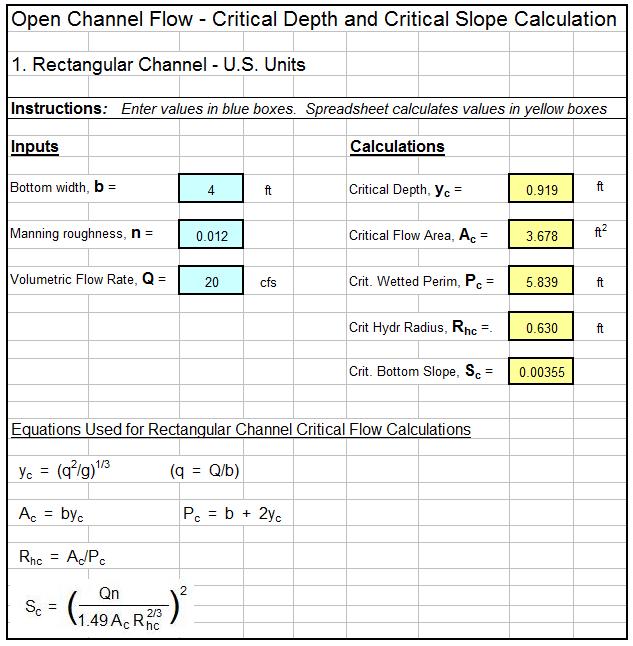
The critical depth open channel flow spreadsheet template shown below can be used to calculate the critical depth and critical slope for a rectangular channel with specified flow rate, bottom width, and Manning roughness coefficient.  Why bother to make these calculations by hand?  This Excel spreadsheet and others with similar calculations for a trapezoidal channel are available in either U.S. or S.I. units at a very low cost in our spreadsheet store.

Critical Depth Open Channel Flow Spreadsheet Screenshot

References

1. Munson, B. R., Young, D. F., & Okiishi, T. H., Fundamentals of Fluid Mechanics, 4th Ed., New York: John Wiley and Sons, Inc, 2002.

2. Chow, V. T., Open Channel Hydraulics, New York: McGraw-Hill, 1959.

3. Bengtson, Harlan H. Open Channel Flow II – Hydraulic Jumps and Supercritical and Nonuniform FlowAn online, continuing education course for PDH credit.


V Notch Weir Calculator Excel Spreadsheet

Where to Find a V Notch Weir Calculator Excel Spreadsheet

To obtain a V notch weir calculator Excel spreadsheet, click here to visit our spreadsheet store. Why use online calculators or hand calculations when you can buy a V-notch weir calculator excel spreadsheet for only $11.95.  Read on for information about Excel spreadsheets that can be used as v-notch weir open channel flow calculators.

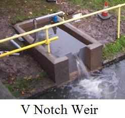
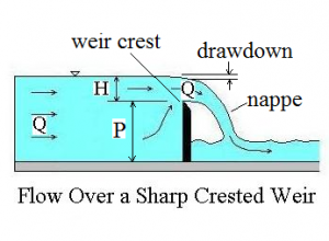
As you can see in the diagrams and picture below, the name, v notch weir, is a good description of the device, simply a v shaped notch in a plate placed in an open channel so that the water is forced to flow through the v notch.  It can be used to measure the open channel flow rate, because the height of water above the point of the v notch can be correlated with flow rate over the weir.  The v-notch weir works well for measuring low flow rates, because the flow area decreases rapidly as the head over the v notch gets small.

Background for Sharp Crested Weirs

Picture for V notch weir calculator excel spreadsheetThe v notch weir is only one of several possible types of sharp crested weirs.  The image at the left shows a picture of a v-notch weir. Acknowledgement of Image Source:              RS Hydro www.rshydro.co.uk                            The diagram below right shows a longitudinal cross-section of a sharp crested weir with several commonly used parameters identified on the diagram.  The weir crest is the term used for the top of the weir.  In the case of a v notch weir, the crest is the point of the v-shaped notch.  The term nappe refers to the sheet of water flowing over the weir.  The equations to bediagram for v notch weir calculator excel spreadsheet  discussed in this article for calculating flow over a v-notch weir require free flow over the weir.  This means that there must be air under the nappe, as shown in the diagram.  The drawdown is the decrease in water level going over the weir caused by the acceleration of the water.  The measurement, H, shown in the diagram is referred to as the head over the weir.  P in the diagram is the height of the weir crest, and the open channel flow rate (also the flow rate over the weir) is shown as Q.

Picture Credit:  U.S. Forest Service

A V Notch Weir Calculator Excel Spreadsheet for a 90 Degree Notch Angle

v notch weir calculator excel spreadsheet diagram

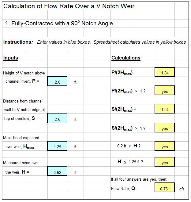
The equation shown below is recommended by the U.S. Dept. of the Interior, Bureau of Reclamation in their Water Measurement Manual (ref #1 below) for calculations with a fully contracted, 90o, v notch, sharp crested weir with free flow conditions and 0.2 ft < H < 1.25 ft.

In U. S. units:  Q = 2.49H2.48, where Q is discharge in cfs and H is head over the weir in ft.

In S.I. units:  Q = 1.36H2.48, where Q is discharge in  m3/s and H is head over the weir in m.

The conditions for the v notch weir to be fully contracted are:

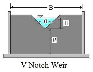
H/P < 0.4,    H/B < 0.2,    P > 1.5 ft (0.45 m),   B > 3 ft (0.9 m)

The diagram above shows the parameters H, P, θ and B for a v notch weir as used for open channel flow rate measurement in a v notch weir calculator excel spreadsheet.

Screenshot of a V Notch Weir Calculator Excel Spreadsheet

The screenshot below shows a v notch weir calculator excel spreadsheet for making 90o, v-notch weir calculations in U.S. units.  Based on specified values for H, P, & S, along with Hmax, the maximum expected head over the weir, the spreadsheet checks on whether the required conditions for fully contracted flow are met and then calculates the flow rate, Q.  This Excel spreadsheet and others for v notch weir calculations are available in either U.S. or S.I. units at a very low cost (only $11.95)  in our spreadsheet store.

References:

1. U.S. Dept. of the Interior, Bureau of Reclamation, 2001 revised, 1997 third edition, Water Measurement Manual, available for online use or download at: http://www.usbr.gov/pmts/hydraulics_lab/pubs/wmm/index.htm.

2. Bengtson, Harlan H., Open Channel Flow III – Sharp Crested Weirs, an online continuing education course for PDH credit, http://www.online-pdh.com/engcourses/course/view.php?id=87

3. Munson, B. R., Young, D. F., & Okiishi, T. H., Fundamentals of Fluid Mechanics, 4th Ed., New York: John Wiley and Sons, Inc, 2002.


Hydraulic Radius Open Channel Flow Excel Spreadsheets

Where to Find Spreadsheets for Hydraulic Radius Open Channel Flow Calculations

For an Excel spreadsheet to use for hydraulic radius open channel flow calculations, click here to visit our spreadsheet store.  Read on for information about hydraulic radius open channel flow calculations.

The hydraulic radius is an important parameter for open channel flow calculations with the Manning Equation.  Excel spreadsheets can be set up to conveniently make hydraulic radius open channel flow calculations for flow through common open channel shapes like those for a rectangular, triangular or trapezoidal flume.  Parameters like trapezoid area and perimeter and triangle area and perimeter are needed to calculate the hydraulic radius as described in the rest of this article.

The hydraulic radius for open channel flow is defined to be the cross sectional area of flow divided by the wetted perimeter.  That is: R = A/P, where A is the cross sectional area of flow, P is the portion of the cross sectional perimeter that is wetted by the flow, and R is the hydraulic radius.  The next several sections will present the equations to calculate A, P, and R for some common open channel shapes, and then discuss the use of Excel spreadsheets for hydraulic radius open channel flow calculations.

Hydraulic Radius Open Channel Flow Calculation for Rectangular Channels

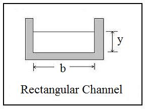
hydraulic radius open channel flow diagram for rectangular channelRectangular channels are widely used for open channel flow, and hydraulic radius open channel flow calculations are quite straightforward for a rectangular cross section. The diagram at the left shows the depth of flow represented by the symbol, y, and the channel bottom width represented by the symbol, b.  It is clear from the diagram that A = by and P = 2y + b.  Thus the equation for the hydraulic radius is: R = by/(2y + b) for open channel flow through a rectangular cross section.


Hydraulic Radius Open Channel Flow Trapezoidal Flume Calculations

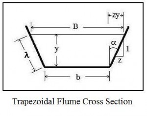
hydraulic radius open channel flow diagram for trapezoidal flumeThe trapezoid is probably the most common shape for open channel flow. Many man-made open channels are trapezoidal flumes, including many urban storm water arroyos in the southwestern U.S.  Also, many natural channels are approximately trapezoidal in cross section. The parameters typically used for the size and shape of a trapezoidal flume in hydraulic radius open channel flow calculations are shown in the diagram at the right. Those parameters, which are used to calculate the trapezoid area and wetted perimeter, are as follows:

  • y is the liquid depth (ft for U.S. & m for S.I.)
  • b is the bottom width of the channel (ft for U.S. & m for S.I.)
  • B is the width of the liquid surface (ft for U.S. & m for S.I.)
  • λ is the wetted length measured along the sloped side (ft for U.S. & m for S.I.)
  • α is the angle of the sloped side from vertical. The side slope also often specified as horiz:vert = z:1.

The common formula for trapezoid area,  A = y(b + B)/2, is a good starting point for obtaining a useful equation for A.  It can be seen from the diagram that B = b + 2zy, so the trapezoid area can be expressed in terms y, b, and z:  A = (y/2)(b + b + 2zy)

Simplifying gives: A = by + zy2.

The wetted perimeter can be expressed as: P = b + 2λ.  The typically unknown sloped length, λ, can be eliminated using the Pythagoras Theorem:

λ2= y2+ (yz)2, or λ = [y2+ (yz)2]1/2 Thus the wetted perimeter is:

P = b + 2y(1 + z2)1/2,   and the hydraulic radius for a trapezoid can be calculated from:

R = (by + zy2)/[b + 2y(1 + z2)1/2]

Hydraulic Radius Open Channel Flow Triangular Flume Calculations

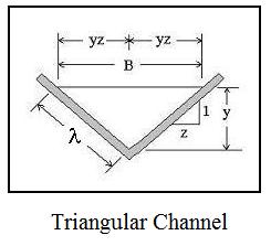
hydraulic radius open channel flow diagram for triangular channelAnother shape used in open channel flow is the triangular flume, as shown in the diagram at the right. The side slope is the same on both sides of the triangle in the diagram.  This is often the case.  The parameters used for hydraulic radius open channel flow calculations with a triangular flume are as follows:

  • B is the surface width of the liquid (ft for U.S. & m for S.I.)
  • λ is the sloped length of the triangle side (ft for U.S. & m for S.I.)
  • y is the liquid depth measured from the vertex of the triangle (ft for U.S. & m for S.I.)
  • z is the side slope specification in the form:  horiz:vert = z:1.

The common formula for triangle area is: A = By/2.  As shown in the figure, however,

B = 2yz, so the triangle area simplifies to: A = y2z.

The wetted perimeter is: P = 2λ , but as with the trapezoidal flume:  λ2= y2+ (yz)2.

This simplifies to the convenient equation: P = 2[y2(1 + z2)]1/2

The hydraulic radius is thus: RH= A/P = y2z/{2[y2(1 + z2)]1/2}

Excel Spreadsheets for Hydraulic Radius Open Channel Flow Calculations

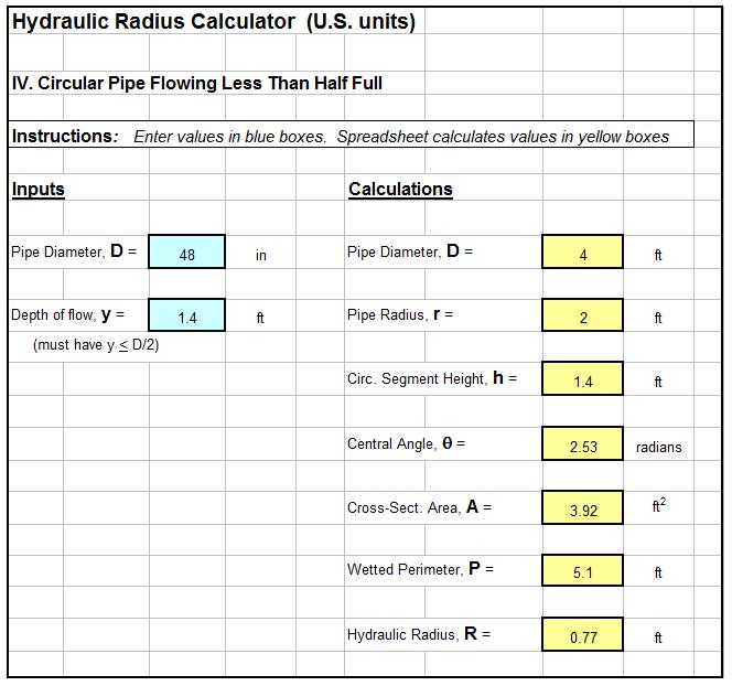
With the equations given in the previous sections, the hydraulic radius can be calculated for a rectangular, triangular or trapezoidal flume if appropriate channel size/shape parameters are known along with the depth of flow.  An Excel spreadsheet like the one shown in the image below, however, can make the the calculations very conveniently.  Excel spreadsheets like the one shown below for use as hydraulic radius open channel flow calculators for rectangular, triangular, and trapezoidal flumes, as well as for partially full pipe flow, are available in our spreadsheet store.

screenshot of hydraulic radius open channel flow Excel spreadsheet

References:

1. Bengtson, Harlan H., Open Channel Flow I – The Manning Equation and Uniform Flow, an online, continuing education course for PDH credit.

2. U.S. Dept. of the Interior, Bureau of Reclamation, 2001 revised, 1997 third edition, Water Measurement Manual.

3. Chow, V. T., Open Channel Hydraulics, New York: McGraw-Hill, 1959.

4. Bengtson, Harlan H., The Manning Equation for Open Channel Flow Calculations,” available as an Amazon Kindle e-book and as a paperback.