Introduction to an ISO 5167 Orifice Coefficient Calculation Spreadsheet
For an ISO 5167 orifice coefficient calculation spreadsheet, click here to visit our spreadsheet store. Read on for information about Excel spreadsheets that can be used to make these ISO 5167 orifice meter calculations.
When ISO 5167 came out in 1991, it included three standard configurations for the pressure taps in an orifice flow meter and equations to calculate the orifice discharge coefficient for a specified ratio of orifice diameter to pipe diameter for any of those three standard pressure tap configurations. This provided greater flexibility for orifice meters, because orifice plates with different orifice diameters could be used in a given orifice meter, while still allowing accurate determination of the orifice discharge coefficient.
Background on ISO 5167 Orifice Coefficient Calculation Spreadsheet
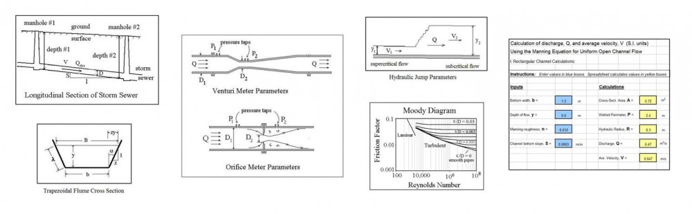
 An orifice meter is a simple device for measuring pipe flow rate through the use of a circular plate with a hole in the center (the orifice plate), held in place between pipe flanges, as shown in the diagram at the left. The fluid pressure decreases downstream of the orifice plate due to the accelerated flow. The pressure difference shown in the diagram as P1 – P2 can be measured and
  used to calculate the flow rate passing through the meter (and thus the pipe flow rate) using the equation shown at the right. This equation allows calculation of pipe flow rate, Q, for measured pressure difference, P1 – P2, and known density of the fluid, ρ, the ratio of orifice diameter to pipe diameter, β, the cross-sectional area of the orifice, Ao, and the orifice discharge coefficient, Cd.
For more details about the orifice, flow nozzle, and venturi meter, see the article, “Excel Spreadsheets for Orifice and Venturi Flow Meter Calculations.”
ISO 5167 Standard Pressure Tap Locations
Prior to ISO 5167 coming out in 1991, the downstream pressure tap of an orifice meter was typically located at the vena contracta (the minimum jet area downstream of the orifice plate) as shown in the diagram above. The correlations in place for determining the orifice discharge coefficient were for the downstream pressure tap at the vena contracta. Unfortunately, the distance of the vena contracta fro the orifice plate changes with orifice diameter, so changing to an orifice plate with a different hole diameter required moving the  downstream pressure tap in order to be able to accurately estimate the orifice discharge coefficient.
The three standard pressure tap configurations identified for orifice flow meters, known as corner taps, flange taps, and D – D/2 taps, are shown in the diagram at the left. As shown in the diagram, the distance of the pressure taps from the orifice plate is given as a fixed distance, or as a function of the pipe diameter, independent of the orifice diameter, so the orifice discharge coefficient can be calculated for several orifice diameters in a given orifice meter.
Equations for ISO 5167 Orifice Coefficient Calculation Spreadsheet
Included in ISO 5167 is an equation allowing calculation of the orifice discharge coefficient, Cd, for known values of β (d/D), Reynolds number, Re, and L1 & L2, where L1 is the distance of the upstream pressure tap from the orifice plate and L2 is the distance of the downstream pressure tap from the orifice plate. For corner taps: L1 = L2 = 0; for flange taps: L1 = L2 = 1″ ; and for D-D/2 taps: L1 = D & L2 = D/2. The ISO 5167 equation for the orifice discharge coefficient is:
Cd – 0.5959 + 0.0312 β2.1 – 0.1840 β8 + 0.0029 β2.5(106/Re)0.75 + 0.0900(L1/D)[β4/(1 – β4)] – 0.0337(L2/D)β3
This equation is usable to find the orifice discharge coefficient for an orifice flow meter with any of the three standard pressure tap configurations, but not for any other arbitrary values of L1 and L2. The introduction of these standard pressure tap configurations and the equation for Cd, allows a given orifice flow meter to conveniently use different size orifice openings and cover a wide flow measurement range.
 An iterative (trial and error) calculation is needed to get a value for Cd, because the upstream velocity needed for Re isn’t known until Cd is known. The ISO 5167 orifice coefficient calculation spreadsheet template shown in the screenshot at the right will calculate the orifice discharge coefficient based on the indicated input information. The spreadsheet uses an iterative calculation procedure. It is necessary to assume a value for Re to start the process and replace that value with the calculated Re as any times as necessary until the two Re values are the same. This ISO 5167 orifice calculation spreadsheet is available in either U.S. or S.I. units at a very low cost in our spreadsheet store.
References:
1. U.S. Dept. of the Interior, Bureau of Reclamation, 2001 revised, 1997 third edition, Water Measurement Manual.
2. International Organization of Standards – ISO 5167-1:2003 Measurement of fluid flow by means of pressure differential devices, Part 1: Orifice plates, nozzles, and Venturi tubes inserted in circular cross-section conduits running full. Reference number: ISO 5167-1:2003.
3. Bengtson, Harlan H., Flow Measurement in Pipes and Ducts, An online continuing education course.
4. Bengtson, Harlan H., “Orifice and Venturi Pipe Flow Meters: for Liquid Flow or Gas Flow,” an Amazon Kindle e-book.