Activated Sludge Secondary Clarifier Design Spreadsheets

Where to Find Activated Sludge Secondary Clarifier Design Spreadsheets

For an Excel spreadsheet for activated sludge secondary clarifier design calculations, click here to visit our spreadsheet store.  Obtain a convenient, easy to use primary and secondary clarifier design spreadsheets for only $11.95.  Read on for information about the use of an Excel spreadsheet for activated sludge secondary clarifier design calculations.

Activated Sludge Secondary Clarifier Design Parameters
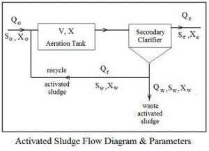
Flow Diagram for Activated Sludge Secondary Clarifier DesignThe parameters typically used for activated sludge secondary clarifier design are the surface overflow rate (SOR), solids loading rate (SLR), and weir overflow rate (WOR).  Activated sludge parameters are shown in the flow diagram at the right.  The equations defining these three parameters are:

SOR = Qo/A,  SLR = (Qo + Qr)X/A, and  WOR = Qo/L,  where:

  • Qo = primary effluent flow rate in MGD (U.S.) or m3/d (S.I.)
  • A = total surface area for secondary clarifier(s) in ft2 (U.S.) or m2 (S.I.)
  • Qr = recycle activated sludge flow rate in MGD (U.S.) or m3/d (S.I.)
  • X = mixed liquor activated sludge solids concentration in mg/L (U.S. or S.I.)
  • L = length of secondary clarifier effluent weir in ft (U.S.) or m (S.I.)

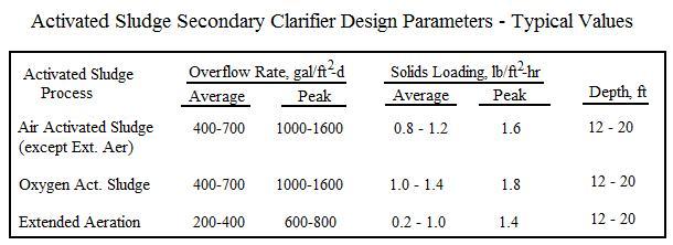
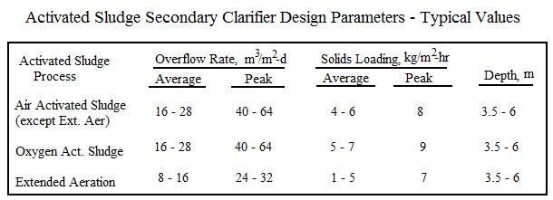
Typical values of surface overflow rate and solids overflow rate for activated sludge secondary clarifier design are shown in the tables below:

Design Parameters for Activated Sludge Secondary Clarifier Design

Activated Sludge Secondary Clarifier Design Parameters

Calculation of Activated Sludge Secondary Clarifier Surface Area

The equation for calculating the needed activated sludge secondary clarifier surface area from a design SOR value with units as shown above is:  A = Qo*106/SOR

The formula for calculating activated sludge secondary clarifier surface area from a design value of SLR with parameter units as shown above is:  A = (Qo + Qr)*8.34*X/SLR

An Excel Spreadsheet as an Activated Sludge Secondary Clarifier Design Calculator

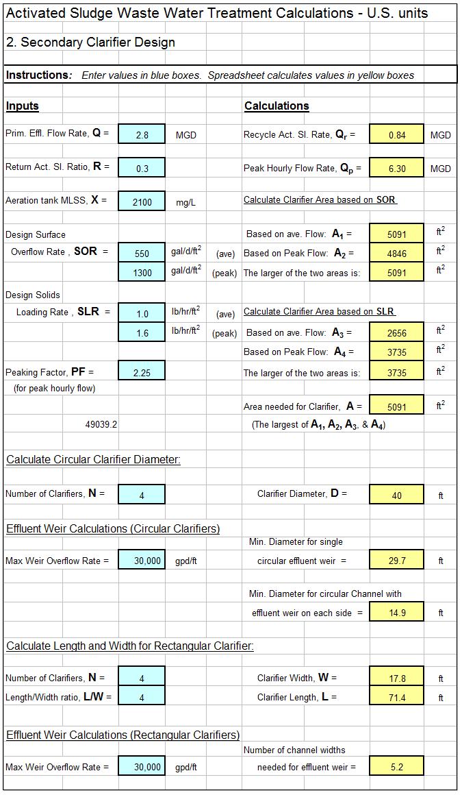
The Excel spreadsheet template shown below can be used to carry out the activated sludge secondary clarifier design calculations described above.   Why bother to make these calculations by hand?  This Excel spreadsheet can handle primary and secondary clarifier surface area calculations and determine diameter for circular clarifier(s) or length and width for rectangular clarifier(s) and is available in either U.S. or S.I. units at a very low cost (only $11.95)  in our spreadsheet store.  These spreadsheets also make weir overflow calculations to aid in effluent weir design.

screenshot of activated sludge secondary clarifier design spreadsheet

Reference

1. Metcalf & Eddy, Inc, (revised by Tchobanoglous, G, Burton, F.L., Stensel, H.D., Wastewater Engineering Treatment and Reuse, 4th Edition, New York, NY, 2003.


Detention Pond Routing Spreadsheet Calculations

Where to Find a Detention Pond Routing Spreadsheet

For detention pond routing spreadsheet to carry out routing calculations and plot inflow and outflow hydrographs, click here to visit our spreadsheet store.  Read on for information about the use of a storm water detention pond routing spreadsheet.


Overview Detention Pond Routing with a Spreadsheet

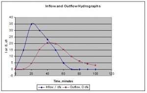
A detention pond routing spreadsheet is used to project an outflow hydrograph from a stormwater Inflow and Outflow Hydrographs from a Detention Pond Routing Spreadsheetdetention pond based on a given inflow hydrograph, stage-storage information for the pond, and stage-outflow information based on the outflow control device.  An output from the routing process is typically a plot of the inflow and outflow hydrographs similar to that shown at the right.  The outflow is often controlled by a rectangular weir, an orifice, and/or a pipe.  In some cases two-stage control is used with perhaps an orifice to provide outflow control for small storms and a weir to control the outflow rate from larger storms.  The routing process should be set up so that changes can be made in outflow control parameters and effects on the outflow hydrograph can then be observed.

Input Information Needed for a Detention Pond Routing Spreadsheet

In addition to an inflow hydrograph like that shown above, stage-storage and stage-outflow information is needed for a detention pond routing spreadsheet.  The stage-storage information would typically be in the form of a table, graph, or equation showing the pond volume, V, as a function of the pond depth, h.  The stage-outflow information is typically in the form of an equation for outflow, O, as a function of pond depth, h, based on the type of outflow control device, as described in the next section.

Stage-Outflow Equations for a detention pond routing spreadsheet

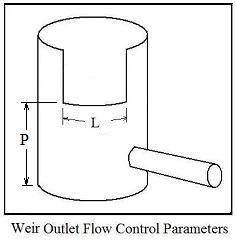
Detention Pond Routing Spreadsheet Weir Outlet DiagramA rectangular weir is one possible outflow control device, often in a riser as shown in the diagram at the left.  The equation for pond outflow  is:     O = CdL(h – P)1.5 where the parameters in the equation are as follow:

  • O = pond outflow = discharge over the rectangular weir in cfs for U.S. units (m3/s for S.I. units)
  • Cd = the discharge coefficient for the weir.  Typical value for U.S. units is 3.3 (1.84 for S.I. units)
  • L = weir length in ft for U.S. units (m for S.I. units)
  • h = stage (depth of water in pond) in ft for U.S. units (m for S.I. units)
  • P = height of weir crest above pond bottom in ft for U.S. units (m for S.I. units)

Equations like this are also available for an orifice outlet, two stage outlet, and pipe outlet.  These equations are given and used in the detention pond routing spreadsheet in either S.I. units or U.S. units in  our spreadsheet store.

The Storage Indication Routing Equation for Detention Pond Routing Spreadsheet Calculations

In addition to the input information described above, a routing equation is needed for a detention pond routing spreadsheet.  A commonly used routing equation is the Storage Indication Equation:

0.5(I1 + I2 )Δt  +  (S1 – 0.5O1Δt)  =  (S2 + 0.5O2Δt) Where:

  • Δt is the time interval used for the inflow and outflow hydrographs in minutes
  • I1 and I2 are successive values of the inflow from the inflow hydrograph (cfs – U.S. or m3/s – S.I.)
  • S1 is the initial value of pond storage (pond volume at the beginning of the storm in cfs – U.S. or m3/s – S.I.)
  • O1 is the initial outflow rate at the beginning of the storm in ft3 – U.S. or m3 – S.I.)
  • S2 and O2 are the pond storage and outflow respectively at time Δt after the beginning of the storm in the same units shown above.

For a given inflow hydrograph, I1, I2 , and all subsequent values of inflow for the duration of the storm are known.  Thus if the initial pond volume, S1, and initial pond outflow, O1, are known, then all of the parameters on the left hand side of the equation are known so the value of the right hand side of the equation (S2 + 0.5O2Δt) can be determined.

Now comes the elegant part of the storage indication routing procedure.  As described above S vs h and O vs h must be available, in the form of tables, graphs or equations.  Thus for any value of h, the parameter, S + 0.5OΔt can be determined and values of S and O can be determined for a known value of S + 0.5OΔt.  Thus, by stepwise calculations in a detention pond routing spreadsheet, the outflow hydrograph (O vs t) can be obtained.

An Excel Spreadsheet as a Pond Routing Calculator

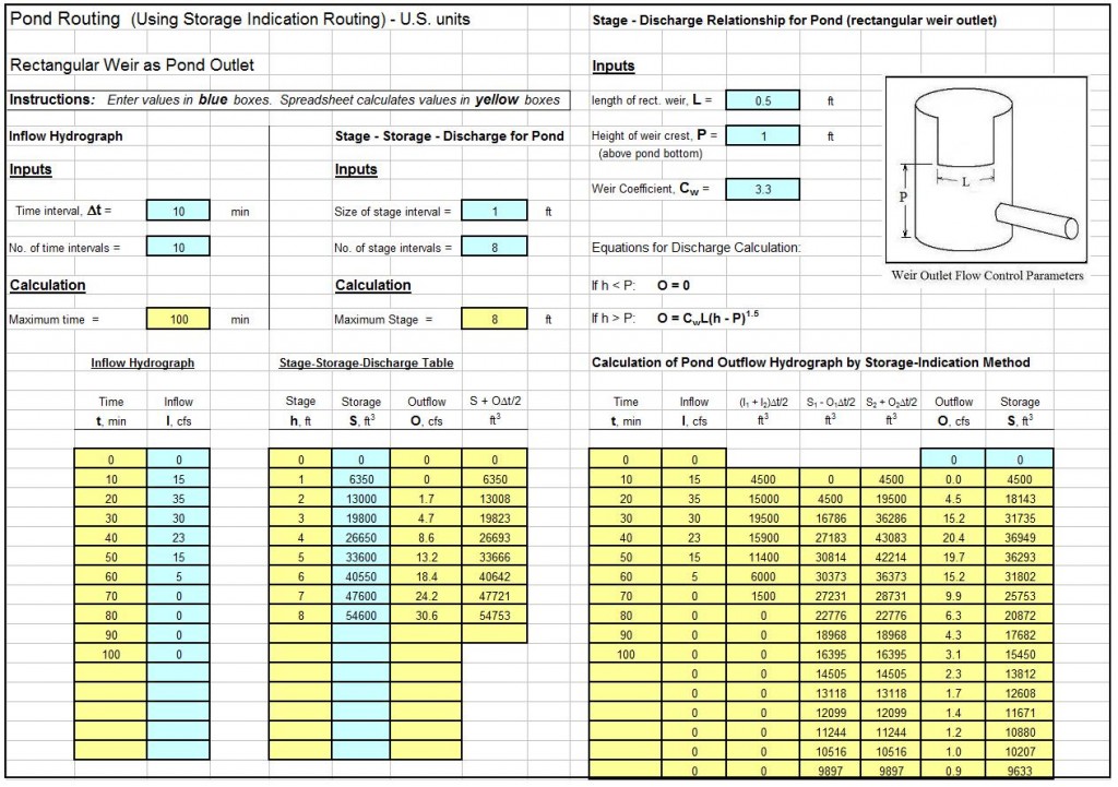
The template shown below is a  detention pond routing spreadsheet to carry out the procedure described above.   Why bother to make these calculations by hand?  This Excel spreadsheet can handle rectangular weir, orifice, two-stage (orifice/weir), pipe outflow control, and two-stage (pipe/weir), and is available in either U.S. or S.I. units at a very low cost in our spreadsheet store.  These spreadsheets also generates a table and graph showing the inflow and outflow hydrographs for a given set of input parameters.

screenshot of a detention pond routing spreadsheet

References

1. McCuen, Richard H., Hydrologic Analysis and Design, 2nd Ed, Upper Saddle River, NJ, 1998.


Minimum Pipe Wall Thickness Calculator Excel Spreadsheet

Where to Find a Minimum Pipe Wall Thickness Calculator Spreadsheet

For an Excel spreadsheet to use as a minimum pipe wall thickness calculator, click here to visit our spreadsheet store.  Read on for information about the use of an Excel spreadsheet as a minimum pipe wall thickness calculator.

The Barlow Formula for a Minimum Pipe Wall Thickness Calculator

The classic Barlow formula for calculating bursting pressure for a pipe is:

P = 2S*T/Do where:

  • Do is the outside diameter of the pipe with units of inches (U.S.) or mm (S.I.)
  • S is the strength of the pipe material with units of psi (U.S.) or N/mm2 (S.I.)
  • T is the wall thickness with units of inches (U.S.) or mm (S.I.)
  • P is the fluid pressure in the pipe with units of psi (U.S.) or MPa (S.I.)

If the ultimate tensile strength of the pipe material is used for S, then P will be the bursting pressure, while P will be the pressure at which permanent deformation of the pipe begins if S is the yield strength of the material.

The Barlow formula can be rearranged to: T = /Do*P/2S to use in a minimum pipe wall thickness calculator for the pipe wall thickness for a given bursting pressure or deformation pressure.

Calculation of Maximum Pipe Operating Pressure

The Barlow formula can be modified to calculate the maximum fluid operating pressure for a given pipe wall thickness and pipe diameter, by incorporation of a safety factor and corrosion allowance as follows:

P = 2S*(T – Tc)/SF*Do

where  SF is a safety factor (dimensionless) and Tc is a corrosion allowance in inches (U.S.) or mm (S.I.).  This equation uses the outside pipe diameter in the calculations, which is convenient, because the outside pipe diameter remains the same for all of the schedules (wall thicknesses) for a given nominal pipe size.  The calculation can be done using the outside pipe diameter (Do) in an equation based on the inside pipe diameter, by using the relationship,  Di =  Do –  2T , to give the equation:

P = 2S*(T – Tc)/SF*(Do –  2T)

Use of Equations in a Minimum Pipe Wall Thickness Calculator

The last equation in the previous section can be rearranged to give a pipe wall thickness formula as follows:

T = (P* SF*Do + 2S*Tc)/(2S + 2P*SF)

An Excel Spreadsheet as a Minimum Pipe Wall Thickness Calculator

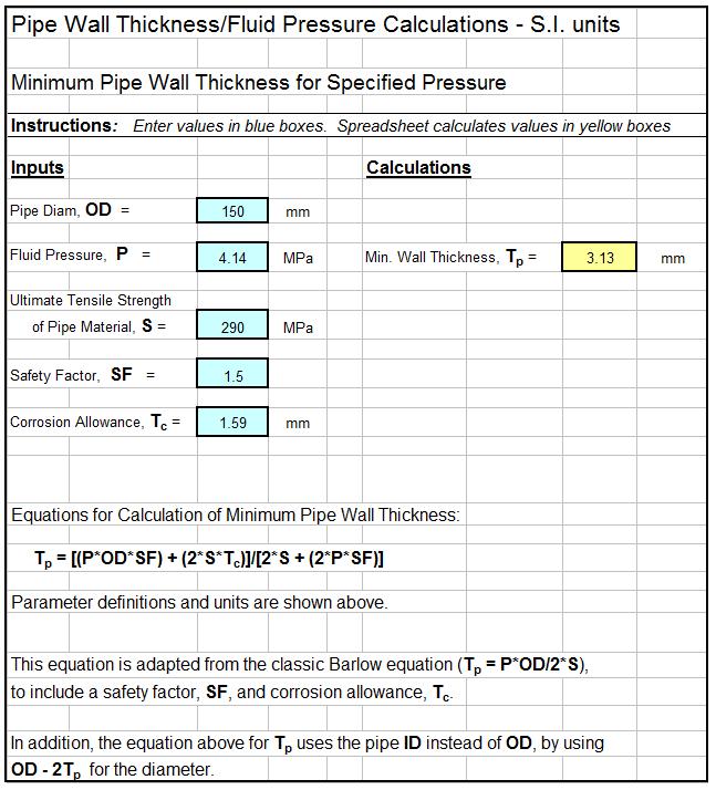
The Excel spreadsheet template shown below can be used as a minimum pipe wall thickness calculator or to calculate the maximum operating pressure in a pipe if the necessary other parameters are known/specified.   Why bother to make these calculations by hand?  This Excel spreadsheet and others for pipe flow calculations are available in either U.S. or S.I. units at a very low cost in our spreadsheet store.

Minimum Pipe Wall Thickness Calculator Spreadsheet