Partially Full Pipe Flow Viscous Liquid Spreadsheet

Where to Find a Partially Full Pipe Flow Viscous Liquid Spreadsheet

To obtain a Partially Full Pipe Flow Viscous Liquid Spreadsheet, click here to visit our spreadsheet store.  This Excel spreadsheet is intended for calculating the flow rate. required diameter, depth of flow, or pipe slope for partially full flow of a viscous liquid in a circular pipe . You can buy a convenient partially full pipe flow viscous liquid spreadsheet for a very reasonable price.  It is available in either U.S. units or S.I. units.  Read on for background information about a partially full pipe flow viscous liquid spreadsheet

Background for a Partially Full Pipe Flow Viscous Liquid Spreadsheet

For information about making calculations for partially full flow of water in a circular pipe, see the post, Partially Full Pipe Flow Calculations Spreadsheet .   That post describes the use of the Manning Equation, which can only be used for the flow of water.  For flow of a liquid with viscosity and/or density different from water, the Darcy-Weisbach Equation should be used.  The parameters and equations for calculating them for partially full pipe flow are shown in the diagram below for flow at a depth greater than the pipe diameter.

Partially Full Pipe Flow Viscous Liquid Spreadsheet Diagram           Figure 1. Parameters and Equations for More Than Half Full Flow

The definition of hydraulic radius and the Darcy-Weisbach equation as applied to partially full pipe flow are shown below.

Partially Full Pipe Flow Viscous Liquid Spreadsheet Equations

 Example Partially Full Pipe Flow Viscous Liquid Spreadsheet

An example partially full pipe flow viscous liquid spreadsheet is partially shown in the image below.  .  This Excel spreadsheet can be used to calculate the pipe flow rate, required diameter, depth of flow or pipe slope for partially full pipe flow of a viscous liquid.   This Excel spreadsheet, as well as others for pipe flow and open channel flow calculations, is available in either U.S. or S.I. units for a very reasonable price in our spreadsheet store.

Partially Full Pipe Flow Viscous Liquid Spreadsheet ScreenshotReferences

1. Bengtson, Harlan H.,  Uniform Open Channel Flow and The Manning Equation, an online, continuing education course for PDH credit.

2. Steel, E.W. & McGhee, T.J., Water Supply and Sewerage, 5th Ed., New York, McGraw-Hill Book Company, 1979

3. Bengtson, H.H., “Manning Equation Partially Filled Circular Pipes,”  An online blog article

4. Bengtson, H.H., “Partially Full Pipe Flow Calculations with Spreadsheets“, available as an Amazon Kindle e-book and as a paperback.

API 570 Piping Inspection Calculations Spreadsheet

Where to Find an API 570 Piping Inspection Calculations Spreadsheet

To obtain an API 570 Piping Inspection Calculations spreadsheetclick here to visit our spreadsheet store.  This Excel spreadsheet is intended for making piping inspection calculations from API 570 and API 574.. You can buy a convenient API 570 piping Inspection calculations spreadsheet  for a very reasonable price.  This spreadsheet calculates required minimum pipe wall thickness, long term corrosion rate, short term corrosion rate, remaining life, and maximum allowable working pressure (MAWP).  It is available in either U.S. units or S.I. units.  Read on for information about using an API 570 piping inspection calculations spreadsheet.

Formulas for API 570 Piping Inspection Calculations Spreadsheet

The required minimum wall thickness for piping  being inspected must be the greater of the calculated pressure design wall thickness and the structural minimum wall thickness.  The pressure design wall thickness is sometimes calculated with the Barlow formula and sometimes it is calculated with the ASME B31.3 formula.  Both are shown below.

Barlow formula ASME B31.3 formula for API 570 piping inspection calculations spreadsheetIn the Barlow formula and the ASME B31.3 formula, P is the design fluid pressure in psig, D is the pipe O.D. in inches, S is the allowable unit stress of the pipe material in psi, E is a longitudinal quality factor, and Y is a coefficient that is a function of the pipe material and the operating temperature.

The structural minimum wall thickness is available in API 574 Table 6 for some pipe materials.  The required minimum pipe wall thickness is the greater of the calculated pressure design wall thickness and the structural minimum wall thickness.

The long term corrosion rate and short term corrosion rate are calculated from values for the current measured pipe wall thickness, a previous pipe wall thickness or the initial pipe wall thickness and the time between the two.  The remaining life of the pipe is calculated as the difference between the current measured pipe wall thickness minus the required minimum pipe wall thickness divided by the corrosion rate.

The maximum allowable working pressure for a pipe is calculated from the formula:

MAWP = 2SEt/D

In this formula, S, E, and D are as defined above and t is the measured pipe wall thickness in inches.

 Example API 570 Piping Inspection Calculations Spreadsheet

An example API Piping Inspection Calculatons spreadsheet is partially shown in the image below.  This Excel spreadsheet can be used to calculate the required minimum pipe wall thickness, corrosion rate, remaining life, and maximum allowable working pressure (MAWP).  This Excel spreadsheet, as well as others for pipe flow calculations, is available in either U.S. or S.I. units for a very reasonable price in our spreadsheet store.

API 570 piping inspection calculations spreadsheet screenshot References:

1. American Piping Institute, AP! 570, Piping Inspection Code: In-service Inspection, Rating, Repair, and Alteration of Piping Systems, 3rd Ed, Nov, 2009

2. American Piping Institute, API 574, Inspection Practices for Piping System Components, 3rd Ed, Nov, 2009.

3. Bengtson, Harlan H., Spreadsheet for API Piping Inspection Calculations, an informational blog article at www.EngineeringExcelTemplates.com

Compressible Pipe Flow Calculator Spreadsheet

Where to Find a Compressible Pipe Flow Calculator Spreadsheet

To obtain a Compressible Pipe Flow Calculator Spreadsheetclick here to visit our spreadsheet store.  Look in the Pipe Flow Calculations category on the Download page.  This Excel spreadsheet is intended to calculate the frictional pressure drop, gas flow rate, or minimum required diameter for adiabatic compressible pipe flow.  You can buy a convenient compressible pipe flow calculator spreadsheet  for a very reasonable price.  Calculations may be made in either U.S. or S.I. units.  Read on for information about using a compressible pipe flow calculator spreadsheet.

Background for Compressible Pipe Flow Calculator Spreadsheet

Compressible pipe flow calculations are needed for gas flow if the density of the gas changes during the flow through the pipe.  The fanno flow equations shown below can be used for calculations with a gas flow that has no heat transfer with surroundings.  Frictional losses are taken into account.  The fanno flow equations are shown below.

Compressible Pipe Flow Calculator Spreadsheet Fanno Flow EquationsExample Compressible Pipe Flow Calculator Spreadsheet

An example compressible pipe flow calculator spreadsheet is partially shown in the image below.  This Excel spreadsheet can be used to calculate the frictional pressure drop, or the gas flow rate, or the required minimum pipe diameter.  This Excel spreadsheet, as well as others for pipe flow calculations, is available for both U.S. or S.I. units for a very reasonable price in our spreadsheet store.

compressible pipe flow calculator spreadsheet screenshotReferences

1.  Munson, B. R., Young, D. F., & Okiishi, T. H., Fundamentals of Fluid Mechanics, 4th Ed., New York: John Wiley and Sons, Inc, 2002.

2. Darcy Weisbach equation history – http://biosystems.okstate.edu/darcy/DarcyWeisbach/Darcy-WeisbachHistory.htm

3. Bengtson, Harlan H.  Fanno Compressible Flow Calculator Spreadsheet,  An online blog article.

4. Bengtson, H.H., Pipe Flow/Friction Factor Calculations with Excel, an online continuing education course for Professional Engineers.


Flow Through Non Circular Ducts Spreadsheet

Where to Find a Spreadsheet for Flow Through Non Circular Ducts

To obtain a spreadsheet for  flow through non circular ductsclick here to visit our spreadsheet store.  Intended for use in calculating flow rate or frictional head loss and frictional pressure drop, you can buy a convenient spreadsheet for  flow through non circular ducts calculations for a very reasonable price.  This spreadsheet makes calculations with the Hagen Poiseuille equation for laminar flow and with the Moody friction factor and the Darcy Weisbach equation for turbulent flow for flow through an annulus and for flow through a rectangular duct.  Turbulent flow calculations can be made for a general non-circular duct with known cross-sectional area and wetted perimeter.  It is available in either U.S. or S.I. units.  Read on for information about a spreadsheet for flow through a non circular duct calculations.

Turbulent Flow Through Non Circular Ducts

The Moody friction factor is used in the Darcy Weisbach equation for turbulent flow through non circular ducts.  The Darcy Weisbach equation is:

Flow Through Non Circular Ducts Equation

Where the hydraulic diameter is used for D in the Darcy Weisbach equation for flow through non circular ducts.  For further discussion of the Moody friction factor and its use in the Darcy Weisbach equation for pipe flow calculations, see the post, “Pipe Flow-Friction Factor Calculations with Excel Spreadsheets.”

Laminar Flow Through Non Circular Ducts

For laminar flow in an annulus or laminar flow in a rectangular duct, the Hagen Poiseuille equation should be used.  For flow through an annulus, it is:

Flow Through Non Circular Ducts Laminar Equations

Hagen Poiseiulle equations for laminar flow through an annulus


 Example Spreadsheet for Flow Through Non Circular Ducts

A spreadsheet for flow through non circular ducts calculations is partially shown in the image below.  This Excel spreadsheet can be used to calculate the frictional pressure drop and head loss or flow rate for flow through an annulus (laminar or turbulent flow), flow through a rectangular duct (laminar or turbulent flow) or flow through a general non circular duct (turbulent flow only).  This Excel spreadsheet, as well as others for pipe flow calculations, is available in either U.S. or S.I. units for a very reasonable price in our spreadsheet store.

Flow Through Non Circular Ducts - Annulus

 Reference:

1. Bengtson, Harlan, “Pressure Drop in a Non Circular Duct”, an online blog article

Spreadsheets for Turbulent and Laminar Flow in Pipes

Where to Find a Spreadsheet for Turbulent and Laminar Flow in Pipes

To obtain a spreadsheet for  Turbulent and Laminar flow in pipesclick here to visit our spreadsheet store.  Intended for use in calculating pipe flow rate, frictional head loss, or required pipe diameter, you can buy a convenient spreadsheet for turbulent or laminar flow in pipes calculations for a very reasonable price.  This spreadsheet makes calculations with the Hagen Poiseuille equation for laminar flow and with the Moody friction factor and the Darcy Weisbach equation for turbulent flow.  It is available in either U.S. or S.I. units.  Read on for information about a spreadsheet for turbulent and laminar flow in pipes calculations.

The Reynolds Number Criterion for Turbulent and Laminar Flow in Pipes

For flow in pipes, the Reynolds number is:  Re  =  DVρ/μ, for any consistent set of units for pipe diameter, D, flow velocity, V, fluid density, ρ, and fluid viscosity, μ.  Pipe flow will be turbulent if the Reynolds number is greater than 4000 and will be laminar if the Reynolds number for the flow is less than 2300.  If the Reynolds number is between 2300 and 4000, the flow may be either laminar or turbulent, depending on factors such as the type of pipe entrance and the roughness of the pipe wall.

Equations for Turbulent and Laminar Flow in Pipes

For discussion of the Moody friction factor and its use in the Darcy Weisbach equation for turbulent pipe flow calculations, see the post, “Pipe Flow-Friction Factor Calculations with Excel Spreadsheets.”  For laminar flow in pipes, the Hagen Poiseuille equation is as follows:             ΔP  =  8μLQ/(Πr4 ),  where  ΔP is the frictional pressure drop in lb/ft2, μ is the fluid viscosity in lb/ft-sec, L is the length of the pipe in ft, Q is the flow rate through the pipe in cfs, and r is the pipe radius in ft.  Note that the Hagen Poiseulle equation is identical with the Darcy Weisbach equation for pipe flow with the Moody friction factor equal to 64/Re.

 Example Spreadsheet for Turbulent and Laminar Flow in Pipes Calculations

A spreadsheet for Turbulent and Laminar Flow in Pipes calculations is partially shown in the image below.  This Excel spreadsheet can be used to calculate the frictional pressure drop and head loss for known pipe flow rate, diameter and length along with fluid density and viscosity and the pipe wall roughness.  It can also be used to calculate pipe flow rate or minimum required pipe diameter if the other parameters are known.  This Excel spreadsheet, as well as others for pipe flow calculations, is available in either U.S. or S.I. units for a very reasonable price in our spreadsheet store.

References

1.  Munson, B. R., Young, D. F., & Okiishi, T. H., Fundamentals of Fluid Mechanics, 4th Ed., New York: John Wiley and Sons, Inc, 2002.

2. Darcy Weisbach equation history – http://biosystems.okstate.edu/darcy/DarcyWeisbach/Darcy-WeisbachHistory.htm

3. Bengtson, Harlan H.  Pipe Flow Calculations with the Darcy Weisbach Equation,  An online blog article.

4. Bengtson, H.H., Pipe Flow/Friction Factor Calculations with Excel, an online continuing education course for Professional Engineers.

5. Bengtson, Harlan, “Advantages of Spreadsheets for Pipe Flow/Friction Factor Calculations“, An Amazon Kindle e-book.

Natural Gas Pipeline Flow Calculation Spreadsheet

Where to Find a Natural Gas Pipeline Flow Calculation Spreadsheet

To obtain a natural gas pipeline flow calculation spreadsheet , click here to visit our spreadsheet store.  Intended for use in making natural gas pipeline design calculations, you can buy a convenient natural gas pipeline flow calculation spreadsheet for a very reasonable price.  This spreadsheet makes calculations with the Weymouth equation, the Panhandle A equation, and the Panhandle B equation, and is available in either U.S. or S.I. units.  Read on for information about a natural gas pipeline flow calculation spreadsheet.

Choice of Equations for Natural Gas Pipeline Flow Calculations

Several different equations are used for natural gas pipeline flow calculations.  If the pressure drop across the pipe is less than 40 % of the average pipeline pressure, then the Darcy Weisbach equation is a possibility.  For longer pipelines with larger pressure drop, the three equations that are in most common use are the Weymouth equation, the Panhandle A equation, and the Panhandle B equation.  The choice among these three equations depends upon the pipeline diameter, the pipe length, and the average pipeline pressure.

The Weymouth Equation for Natural Gas Pipeline Flow Calculations

The Weymouth equation was the first of the three to be developed and was the first equation for natural gas pipeline flow calculations that didn’t require an iterative calculation to get a value for the friction factor.  The Weymouth equation is:

Where:

  • Q is the natural gas pipeline flow rate in SCFD
  • E is the pipeline efficiency
  • Tb is the base temperature in oR
  • Pb is the base pressure in psia
  • P1 is the inlet pressure in psia
  • P2 is the outlet pressure in psia
  • G is the specific gravity of the natural gas relative to air
  • Tf is the pipeline temperature of the flowing natural gas in oR
  • L is the pipeline length in miles
  • Le  is the effective pipeline length in  miles
  • ΔH is the height of the pipeline exit above the pipeline inlet in ft
  • Z is the compressibility factor of the natural gas at pipeline T & P
  • D is the pipeline diameter in inches.

Example Spreadsheet for Natural Gas Pipeline Flow Calculations

A spreadsheet for Natural Gas Pipeline Flow Calculations is partially shown in the image below.  It can be used to calculate the natural gas pipeline flow rate with the Weymouth equation, the Panhandle A equation and the Panhandle B equation.  This Excel spreadsheet, as well as others for pipe flow calculations, is available in either U.S. or S.I. units for a very reasonable price in our spreadsheet store.

Natural Gas Pipeline Flow Calculation


References for Further Information:

1. Crane Co.,  (1988),  “Flow of Fluids through Valves, Fittings and Pipes,  Technical Paper 401.

2.  GPSA  (Gas Processors Suppliers Association),  (1988),  Engineering Data Book, 11th Ed.

3. Bengtson, Harlan H., (2016), “Natural Gas Pipeline Flow Calculations,”  available as a paperback book or as an Amazon Kindle ebook.

4.  Bengtson, Harlan H.,  (2017),   “Pipe Flow/Friction Factor Calculations with Spreadsheets“,  available as a paperback book or as an Amazon kindle e-book.

5. Bengtson, Harlan H., (2014),  “Natural Gas Pipeline Flow Calculation Spreadsheet“, a blog article at www.EngineeringExcelTemplates.com.


A Spreadsheet for Choked Air Flow Calculation

Where to Find a Spreadsheet for Choked Air Flow Calculation

To obtain a spreadsheet for choked air flow calculations click here to visit our spreadsheet store.  Intended for use in making fanno flow calculations with adiabatic compressible flow of air, you can buy a convenient spreadsheet for choked air flow calculations for a very reasonable price.  This spreadsheet will also calculate the frictional pressure drop, and is available in either U.S. or S.I. units.  Read on for information about a choked air flow calculation spreadsheet for compressible pipe flow.

Conditions for Choked Air Flow Calculation with a Fanno Flow Excel Spreadsheet

For flow of air in a pipe with the frictional pressure drop less than 20% of the inlet air pressure, satisfactory results can be obtained using incompressible flow calculations with the Darcy-Weisbach equation.  For background information on that type of calculation, see the article, “Pipe Flow-Friction Factor Calculations with Excel Spreadsheets.”  If the frictional pressure drop is more than 20% of the incoming air pressure, then Fanno Flow equations should be used, as discussed here using a Fanno Flow Excel spreadsheet.

With adiabatic compressible flow conditions, the maximum air flow rate that can pass through a pipe is that which occurs when the exit Mach number is 1.0.  This is referred to as “choked flow.”

Equations for Choked Air Flow Calculations with a Fanno Flow Excel Spreadsheet

Shown below are the primary equations used in the fanno flow excel spreadsheet being discussed here for compressible flow of air in a pipe.  These equations are for compressible pipe flow with negligible heat transfer with the surroundings, but including effects of friction in the flow.

Fanno Flow Excel Spreadsheet EquationsThe parameters in these fanno flow equations are as follows:

  • f = Moody friction factor
  • L = pipe length
  • D = pipe diameter
  • k = adiabatic constant for the flowing air
  • M = mach number
  • T = air temperature
  • P = air pressure
  • ρ = air density

Parameters with an asterisk refer to conditions at the “choke point” in the pipe, where the Mach number is 1.

Screenshot for a Choked Air Flow Calculation Spreadsheet Using Fanno Flow Equations

The screenshot below shows part of a fanno flow excel spreadsheet for making compressible air flow calculations.  These calculations are for air flow in a pipe, in S.I. units. This Excel spreadsheet and others for compressible pipe flow calculations in a fanno flow excel spreadsheet are available in either U.S. or S.I. units at a very reasonable cost  in our spreadsheet store.Choked Air Flow Calculation Spreadsheet

Reference:

Bengtson, Harlan H.,  “Compressible Flow Pressure Drop Calculator Spreadsheet,” an online blog article

Flow Through Annulus Calculator Excel Spreadsheet

Where to Find an Excel Spreadsheet Flow Through Annulus Calculator

For an Excel spreadsheet liquid flow through annulus calculatorclick here to visit our spreadsheet store.  Look in the “Non-Circular Duct flow Calculations” category.  Obtain a convenient, easy to use spreadsheet liquid flow through annulus calculator at a reasonable price. Read on for information about the use of Excel spreadsheets to calculate pressure drop or liquid flow rate for annulus flow.

Friction Factor-Pipe Flow Background for a Liquid Flow Through Annulus Calculator

A liquid flow through annulus calculator spreadsheet uses calculations that are very similar to those for flow through a pipe.  The main difference is use of the hydraulic diameter for flow through an annulus in place of the pipe diameter as used for pipe flow.  For details of pipe flow calculations, see the article, “Friction Factor/Pipe Flow Calculations with Excel Spreadsheets.”

Calculation of the Hydraulic Diameter for a Liquid Flow Through Annulus Calculator

The general definition of hydraulic diameter for flow through a non-circular cross-section is:                               DH = 4(A/P),    where:

  • DH is the hydraulic diameter in ft (m for S.I. units)
  • A is the cross-sectional area of flow in sq ft (sq m for S.I. units)
  • P is the wetted perimeter in ft (m for S.I. units)

For a flow through annulus calculator:

  • A = (π/4)(Do2 –  Di2)
  • P  =  π(Do + Di)

Where Do is the inside diameter of the outer pipe and Di is the outside diameter of the inner pipe.  Substituting for A and P in the definition of  DH and simplifying gives:

DH =  Do – Di

Equations for the Liquid Flow Through Annulus Calculator

The Darcy Weisbach equation for flow in an annulus is:  hL = f(L/DH)(V2/2g), with the parameters in the equation as follows: hL is the frictional head loss for flow of a liquid at average velocity, V, through an annulus of length, L, and hydraulic diameter, DH .  The Reynolds number for the flow (Re) and the relative roughness of the pipe (Manning roughness coefficient /pipe diameter, ε/D) are needed to get a value for the friction factor, f.  The Moody friction factor diagram and equations for calculating the friction factor, f, are presented and discussed in the article, “Friction Factor/Pipe Flow Calculations with Excel Spreadsheets.”

Spreadsheets for the Liquid Flow Through Annulus Calculator

The Excel spreadsheet screenshot below shows a liquid flow through annulus calculator spreadsheet for calculation of the head loss and frictional pressure drop for flow of a liquid through an annulus.  Based on the input values for the annulus diameters and length as well as liquid flow rate and properties, the spreadsheet will calculate the head loss and frictional pressure drop.

For low cost, easy to use spreadsheets to make these calculations as well as similar calculations for liquid flow in an annulus or for pipe flow calculations, in S.I. or U.S. units, click here to visit our spreadsheet store.

liquid flow through annulus calculator spreadsheetReferences

1.  Munson, B. R., Young, D. F., & Okiishi, T. H., Fundamentals of Fluid Mechanics, 4th Ed., New York: John Wiley and Sons, Inc, 2002.

2. Bengtson, H.H., Pipe Flow/Friction Factor Calculations with Excel, an online continuing education course for Professional Engineers.

3.  Bengtson, Harlan H.,  Advantages of Spreadsheets for Pipe Flow/Friction Factor Calculations,  an e-book available through Amazon.com.

Minimum Pipe Wall Thickness Calculator Excel Spreadsheet

Where to Find a Minimum Pipe Wall Thickness Calculator Spreadsheet

For an Excel spreadsheet to use as a minimum pipe wall thickness calculator, click here to visit our spreadsheet store.  Read on for information about the use of an Excel spreadsheet as a minimum pipe wall thickness calculator.

The Barlow Formula for a Minimum Pipe Wall Thickness Calculator

The classic Barlow formula for calculating bursting pressure for a pipe is:

P = 2S*T/Do where:

  • Do is the outside diameter of the pipe with units of inches (U.S.) or mm (S.I.)
  • S is the strength of the pipe material with units of psi (U.S.) or N/mm2 (S.I.)
  • T is the wall thickness with units of inches (U.S.) or mm (S.I.)
  • P is the fluid pressure in the pipe with units of psi (U.S.) or MPa (S.I.)

If the ultimate tensile strength of the pipe material is used for S, then P will be the bursting pressure, while P will be the pressure at which permanent deformation of the pipe begins if S is the yield strength of the material.

The Barlow formula can be rearranged to: T = /Do*P/2S to use in a minimum pipe wall thickness calculator for the pipe wall thickness for a given bursting pressure or deformation pressure.

Calculation of Maximum Pipe Operating Pressure

The Barlow formula can be modified to calculate the maximum fluid operating pressure for a given pipe wall thickness and pipe diameter, by incorporation of a safety factor and corrosion allowance as follows:

P = 2S*(T – Tc)/SF*Do

where  SF is a safety factor (dimensionless) and Tc is a corrosion allowance in inches (U.S.) or mm (S.I.).  This equation uses the outside pipe diameter in the calculations, which is convenient, because the outside pipe diameter remains the same for all of the schedules (wall thicknesses) for a given nominal pipe size.  The calculation can be done using the outside pipe diameter (Do) in an equation based on the inside pipe diameter, by using the relationship,  Di =  Do –  2T , to give the equation:

P = 2S*(T – Tc)/SF*(Do –  2T)

Use of Equations in a Minimum Pipe Wall Thickness Calculator

The last equation in the previous section can be rearranged to give a pipe wall thickness formula as follows:

T = (P* SF*Do + 2S*Tc)/(2S + 2P*SF)

An Excel Spreadsheet as a Minimum Pipe Wall Thickness Calculator

The Excel spreadsheet template shown below can be used as a minimum pipe wall thickness calculator or to calculate the maximum operating pressure in a pipe if the necessary other parameters are known/specified.   Why bother to make these calculations by hand?  This Excel spreadsheet and others for pipe flow calculations are available in either U.S. or S.I. units at a very low cost in our spreadsheet store.

Minimum Pipe Wall Thickness Calculator Spreadsheet


Pipe Flow-Friction Factor Calculator Excel Spreadsheet

Where to Find a Pipe Flow-Friction Factor Calculator Excel Spreadsheet

For a pipe flow-friction factor calculator Excel Spreadsheet, click here to visit our spreadsheet store.  Why read values from a Moody diagram, make iterative calculations to get friction factor, or use online calculators, when you can get a pipe flow-friction factor calculator Excel Spreadsheet for only $19.95?  Read on for information about the Darcy Weisbach equation and its use in an Excel spreadsheet as a friction factor/pipe flow calculator.

Excel spreadsheets are very convenient for Darcy Weisbach equation/pipe flow calculations, such as frictional pressure drop calculation or use of a friction factor calculator, at least in part because some of the calculations require iterative solutions.  The Darcy Weisbach equation is applicable to pressure flow in pipes, rather than gravity flow (as in sewer pipes), which is handled by open channel flow equations like the Manning equation.  The Darcy Weisbach equation provides the relationship among the following parameters: pipe diameter and length, pipe flow rate, and  frictional pressure drop or head loss.  Any one of these can be calculated if the others are known along with the density and viscosity of the fluid.

A Friction Factor Calculator and the Darcy Weisbach Equation

Moody diagram for pipe flow-friction factor calculator excel spreadsheetThe Darcy Weisbach equation  is hL= f(L/D)(V2/2g), with the parameters in the equation as follows: hLis the frictional head loss for flow of a fluid at average velocity, V, through a pipe of length,L, and diameter,D.  The Reynolds number for the flow (Re) and the relative roughness of the pipe (e/D) are needed to get a value for the friction factor,f.  The Moody Diagram at the right shows the nature of the dependence of the friction factor, f,  on Re and e/D.

Friction factor equations for pipe flow-friction factor calculator Excel spreadsheet
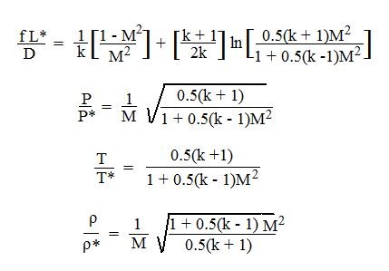
Equations for f as a function of Re and e/D would be more convenient than a graph like the Moody Diagram for use with Excel spreadsheets making  pipe flow calculations with the Darcy Weisbach equation.  Such equations are shown in the box at the left, giving the relationships between Moody friction factor and Re & e/D for four different portions of the Moody diagram.  The four portions of the Moody diagram are:

  • laminar flow(Re < 2100 – the straight line at the left side of the Moody
  • smooth pipe turbulent flow(the dark curve labeled “smooth pipe” in the Moody diagram – f is a function of Re only in this region)Pipe Roughness Values for Pipe Flow-Friction Factor Calculator Excel Spreadsheet
  • completely turbulent region(the portion of the diagram above and to the right of the dashed line labeled “complete turbulence” – f is a function of e/D only in this region)
  • transition region(the portion of the diagram between the “smooth pipe” solid line and the “complete turbulence” dashed line – f is a function of both Re and e/D in this region and this is not an explicit equation for f)

The table above right gives pipe roughness values for several common pipe materials.  These can be used to calculate the pipe roughness ratio, e/D.

For a low cost Moody friction factor calculator download, that will calculate f for Reynolds number above 2100, see: www.engineeringexceltemplates.com

Frictional Head Loss and Frictional Pressure Drop Calculation

After using the Moody friction factor calculator to get a value for the friction factor, f, frictional head loss calculation is quite straightforward if the pipe length & diameter and average flow velocity are known.  You simply need to substitute values for L, D, V, and f into the Darcy Weisbach equation [hL= f(L/D)(V2/2g) ].  The Darcy Weisbach equation is a dimensionally consistent equation, so any consistent set of units can be used.  For U.S. units, hL, L, and D are typically in ft, V is in ft/sec, and g is 32.2 ft/sec2.  For S.I. units, hL, L and D are typically in m, V is in m/s, and g is 9.81 m/s2.  If volumetric flow rate, Q, is known rather than average velocity, V, then V can be calculated from:

equation to use with pipe flow-friction factor calculator Excel spreadsheet

Frictional pressure drop calculation from frictional head loss is done through the equation:

equations for use with pipe flow-friction factor calculator Excel spreadsheet

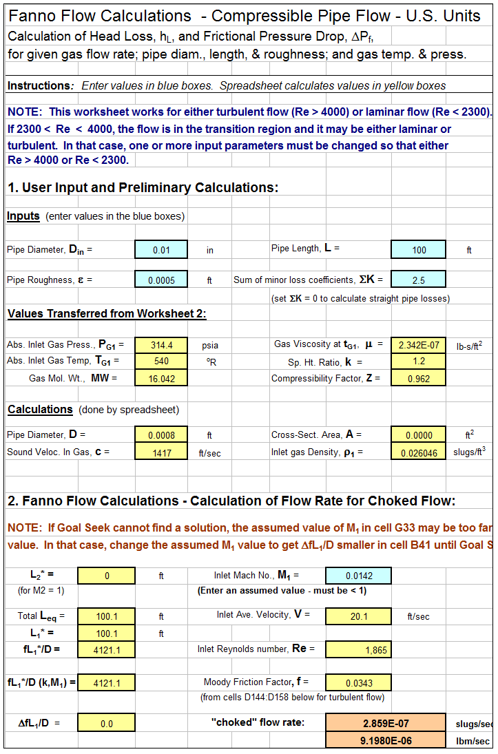
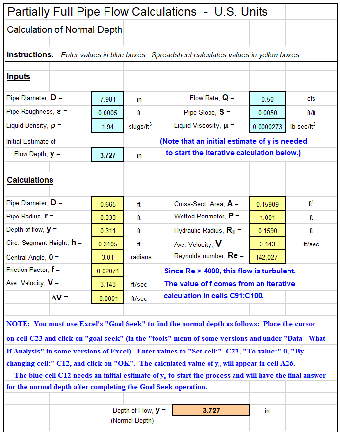
A Screenshot for a Pipe Flow-Friction Factor Calculator Excel Spreadsheet

The Excel spreadsheet screenshot below shows a pipe flow-friction factor calculator excel spreadsheet that is available as part of the “Pipe Flow-Friction Factor Calculation Package,”  at our spreadsheet store in either U.S. or S.I. units at a very low cost (only $16.95).  This spreadsheet package has three worksheets: one to calculate frictional head loss and pressure drop for known pipe diameter, length & material and flow rate; one to serve as a pipe flow rate calculator for known head loss/pressure drop, and pipe diameter, length & material; and one to calculate required pipe diameter for known head loss/pressure drop, flow rate, and pipe length & material.

spreadsheet screenshot for pipe flow friction factor calculator Excel spreadsheet
References

1.  Munson, B. R., Young, D. F., & Okiishi, T. H., Fundamentals of Fluid Mechanics, 4th Ed., New York: John Wiley and Sons, Inc, 2002.

2. Darcy Weisbach equation history – http://biosystems.okstate.edu/darcy/DarcyWeisbach/Darcy-WeisbachHistory.htm

3. Source for pipe roughness values – http://www.efunda.com/formulae/fluids/roughness.cfm

4. Bengtson, H.H., Pipe Flow/Friction Factor Calculations with Excel, and online continuing education course for Professional Engineers.

5. Bengtson, Harlan H., “Pipe Flow Friction Factor Calculations with Spreadsheets,” available as an Amazon Kindle e-book and as a paperback.

6. Bengtson, Harlan H., “Pipe Flow Calculations with the Darcy Weisbach Equation“, an online blog article
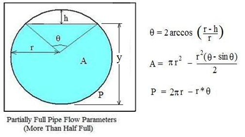