Proportional Sutro Weir Design Calculation Excel Spreadsheet

Where to get a Proportional Sutro Weir Design Calculation Excel Spreadsheet

For a proportional sutro weir design calculation Excel spreadsheet in either U.S. or S.I. units, click here to visit our spreadsheet store.  Obtain convenient, easy to use spreadsheets for proportional sutro weir design calculations at reasonable prices. Read on for information about the use of a proportional sutro weir design calculation Excel spreadsheet.

Principles of a Proportional Sutro Weir Design Calculation Excel Spreadsheet

For the commonly used rectangular weir or V-notch weir, the flow rate over the weir Diagram for proportional sutro weir design calculation excel spreadsheetincreases as the head over the weir increases, but the flow rate increases at a faster rate than the head over the weir.  For some applications, it is desirable for the flow rate over a weir to be proportional to the head over the weir.  The sutro weir, also known as a proportional weir accomplishes this by having the width of the opening above the weir crest decrease with increasing head over the weir crest as shown in the diagram of a sutro weir at the right.  Equations that can be used for proportional sutro weir design are discussed in the next section.

Equations for Proportional Sutro Weir Design Calculation Excel Spreadsheet

Equations for the base width and base height of a sutro weir are as follows:

base height equation for proportional sutro weir design calculation Excel spreadsheet

base width equation for proportional sutro weir design calculation Excel spreadsheet

  • Wb  =  base width in ft (m for S.I. units)
  • Hb  =  base height in ft (m for S.I. units)
  • Hc  =  max height or curved portion of weir in ft (m for S.I. units)
  • Qmax  =  design maximum flow over the weir in cfs (m3/s for S.I. units)
  • Qmin  =  design minimum flow over the weir in cfs (m3/s for S.I. units)
  • g = acceleration of gravity = 32.17 ft/s/s (9.81 m/s/s for S.I. units)

The equation for the curved portion of a proportional sutro weir is:

Curve Equation for proportional sutro weir design calculation Excel spreadsheet

X and Z are position parameters as shown in the diagram above.  They will have the same units as Wb .

A Screenshot for a Proportional Sutro Weir Design Calculation Excel Spreadsheet

For a proportional sutro weir design calculation Excel spreadsheet with calculations in S.I. or U.S. units, or for other spreadsheets for open channel flow measurement calculations, see: www.engineeringexceltemplates.com

The Excel spreadsheet screenshot below shows part of a spreadsheet for proportional sutro weir design calculations, available  at our spreadsheet store in either U.S. or S.I. units at a very reasonable price.

 Screenshot of Proportional Sutro Weir Design Calculation Excel Spreadsheet

Reference

1, U.S. DOT, Fed Highway Admin, Urban Design Manual, Circular No. 22, 2nd Ed. 2001  (Publ. No. FHWA-NHI-010021-HEC-22)

2. Bengtson, Harlan H., Proportional Weir Design Equations,” an online blog article

Wastewater Lagoon Design Spreadsheets

Where to get Wastewater Lagoon Design Spreadsheets

For wastewater lagoon design spreadsheets in either U.S. or S.I. units, click here to visit our spreadsheet store.  Obtain convenient, easy to use spreadsheets for wastewater lagoon design calculations at reasonable prices. Read on for information about the use of Excel spreadsheets for wastewater lagoon design.  Three types of wastewater lagoons that will be discussed next are the anaerobic lagoon, the facultative lagoon, and the maturation pond.

Anaerobic Wastewater Lagoon Design

Anaerobic lagoons are most useful for incoming wastewater with a high BOD content.  If present, an anaerobic lagoon would typically be the first type of treatment, often followed by facultative and or maturation ponds.  Anaerobic lagoons are deeper than facultative or maturation ponds, usually 8 to 15 ft.  Anaerobic wastewater lagoon Design is usually based on volumetric loading (kg BOD/day/m3 or  lb BOD/day/1000 ft3).  A specified minimum hydraulic retention time may also be used.

Facultative Wastewater Lagoon Design

The classic type wastewater treatment lagoon is the facultative pond.  It is aerobic at the  top with an anaerobic sediment layer at the bottom.  Algae growing in the lagoon are important for maintaining dissolved oxygen in the pond.  There are often one or more primary facultative ponds and one or more secondary ponds.  A typical three cell layout for two primary cells and one secondary cell is shown in the diagram below.  A well designed and operated facultative lagoon system can provide secondary level treatment if algae are removed from the effluent.  Facultative wastewater lagoon design is typically based on surface loading (kg BOD/day/ha or lb BOD/day/acre).  A specified minimum hydraulic detention time is often used as a design factor also.Wastewater Lagoon Design - Three Cell Layout

Maturation Wastewater Lagoon Design

A maturation pond will typically be the last type of pond in a wastewater lagoon system if it is present.  There is usually little additional BOD removal in a maturation pond.  Its primary function is disinfection/reduction in bacterial content.  Maturation pond design is often based on required reduction in coliform bacteria with perhaps a minimum hydraulic retention time.

A Screenshot for a Wastewater Lagoon Design Spreadsheet

For a wastewater lagoon design spreadsheet with calculations in S.I. or U.S. units, or for other spreadsheets for activated sludge wastewater treatment calculations, see: www.engineeringexceltemplates.com

The Excel spreadsheet screenshot below shows part of a spreadsheet for wastewater lagoon design calculations, available  at our spreadsheet store in either U.S. or S.I. units at a very reasonable price.

Screenshot of wastewater lagoon design spreadsheet

References

1.  USEPA, Principles of Design and Operations of Wastewater Treatment Pond Systems for Plant Operators, Engineers, and Managers, EPA/600/R-11/088, August 2011.

2. Mara, D. & Pearson, H., Design Manual for Waste Stabilization Ponds in Mediterranean Countries, Lagoon Technology International Ltd, 1998.


Pipe Culvert Design Spreadsheet Calculations

Where to get a circular pipe culvert design spreadsheet

For pipe culvert design spreadsheets in either U.S. or S.I. units, click here to visit our spreadsheet store.  Obtain convenient, easy to use spreadsheets for culvert design calculations at reasonable prices. Read on for information about the use of Excel spreadsheets for circular culvert design.

Inlet Control and Outlet Control for a Pipe Culvert Design Spreadsheet

One of the general conditions for pipe culvert design calculations is inlet control, in which the flow rate through the culvert is controlled at the inlet end of the culvert by the culvert diameter and other inlet conditions.  The other general condition is outlet control, in which the flow rate is controlled by the outlet conditions and the entire length of the culvert.

Pipe Culvert Inlet Control Design Spreadsheet Calculations

An equation that relates culvert parameters for inlet control conditions in a pipe culvert design spreadsheet is:

Culvert Design Equation for Inlet Control Conditionswhere:

  • HW = headwater depth above inlet invert (ft – U.S. or m – S.I.)
  • D = inside height of the culvert (ft – U.S. or m – S.I.)
  • Q = discharge (cfs – U.S. or m3/s – S.I.)
  • A = cross-sectional area of culvert (ft2 – U.S. or m2 – S.I.)
  • S = culvert slope (dimensionless)
  • K1 = 1.0 for U.S. units or 1.811 for S.I. units
  • Ks = slope constant = -0.5 for a non-mitered or + 0.7 for a mitered inlet
  • Y and c are constants dependent on the type of culvert and type of inlet.

Pipe Culvert Outlet Control Design Calculations

An equation that relates culvert parameters for outlet control conditions in a pipe culvert design spreadsheet is:

Head Loss Equation for Outlet Control Culvert DesignWhere:

  • hL = the head loss in the culvert barrel for full pipe flow (ft – U.S. or m – S.I.)
  • Ku = 29 for U.S. units or 19.63 for S.I. units
  • n = Manning roughness coefficient for the culvert material
  • L = length of the culvert barrel (ft – U.S. or m – S.I.)
  • R = hydraulic radius of the full culvert barrel = A/P (ft – U.S. or m – S.I.)
  • A = cross-sectional area of the culvert barrel (ft2 – U.S. or m2 – S.I.)
  • P = perimeter of the culvert barrel, ft or m
  • V = velocity in the culvert barrel, ft/sec or m/s
  • Ke = loss coefficient for pipe entrance

A spreadsheet screenshot for pipe culvert design calculations


The Excel spreadsheet screenshot below shows part of a spreadsheet for circular culvert design calculations based on inlet control.   Based on the indicated input values, the spreadsheet will calculate the minimum required pipe culvert diameter and the headwater depth for the next larger standard culvert diameter.

For low cost, easy to use spreadsheets to make these calculations in S.I. or U.S. units, click here to visit our spreadsheet store.

screenshot for pipe culvert design spreadsheet

References

1.  Hydraulic Design of Highway Culverts,Third Edition,  Publication No. FHWA-HIF-12-026, U.S. DOT/Federal Highway Administration, April, 2012.

2. Bengtson, Harlan H., “Spreadsheets for Circular Culvert Design.”, an online article.

Spreadsheets for Lime Soda Water Softening Calculations

Where to Find Spreadsheets for Lime Soda Water Softening Calculations

For Excel spreadsheets to make lime soda water softening calculations, click here to visit our spreadsheet store.  Obtain convenient, easy to use spreadsheets for lime soda water softening calculations at reasonable prices. Read on for information about the use of Excel spreadsheets for this application.

Water Hardness Background for Lime Soda Water Softening

Hardness in water is caused by divalent cations, primarily Ca++ and Mg++.  Water hardness is sometimes classified in terms of the cation as calcium hardness or magnesium hardness.  The sum of the two is typically referred to as total hardness or simply hardness.  For lime soda water softening chemistry it is also necessary to have knowledge about the anions in the water.  Hardness due to Ca++ or Mg++ together with carbonate (CO3=) or bicarbonate (HCO3) is called carbonate hardness.  At typical drinking water pH, the anion for carbonate hardness is almost completely bicarbonate.  Hardness due to Ca++ or Mg++ together with any anion other than carbonate/bicarbonate is called noncarbonate hardness.

The two most widely used methods for softening water (reducing hardness to an acceptable level) are lime soda water softening and ion exchange softening.  Ion exchange softening is typically used for groundwater softening and for home water softeners, while lime soda water softening is the usual method of choice for a surface water source.  This article is about lime soda water softening.

Lime Soda Water Softening Background

Lime soda softening uses addition of lime and soda ash to remove Ca++ and Mg++ ions, bringing their concentration down to an acceptable level.  The lime may be in the form of quicklime (CaO) or hydrated lime (Ca(OH)2), also called slaked lime.  Soda Ash is Na2CO3.  Calcium ions are removed be bringing the pH level up enough to convert Ca(HCO3)2 to CaCO3, which is relatively insoluble in water and precipitates out down to a residual level of about 30 to 40 mg/L.  Magnesium is precipitated out as Mg(OH)2.  Some lime soda softening processes require addition of carbon dioxide (recarbonation) at one or more points in the process to reduce the pH.

Lime Soda Water Softening Process Alternatives

Three common alternative processes for lime soda water softening are i) two-stage, excess lime treatment, ii) single-stage, selective calcium removal, and iii) split treatment.  Flow diagrams and a brief description of each follows.

Flow diagram for lime soda water softening with excess lime

The two-stage, excess lime softening process provides the most complete softening.  It is capable of removing calcium and magnesium carbonate and noncarbonate hardness, down to the solubility limits of about 30 to 40 mg/L of calcium hardness and about 10 mg/L of magnesium hardness.

Flow diagram for lime soda water softening with selective calcium removal

The single-stage, selective calcium removal process is suitable for water sources with 40 mg/L or less of magnesium hardness.  As indicated by its name, this process removes only calcium hardness and has no effect on magnesium hardness.  A suitably softened water should have less than 40 mg/L of magnesium hardness, so this is the limiting factor for use of this simpler process, which requires less chemicals.

Flow diagram for lime soda water softening with split treatment

The split treatment softening process illustrated in the diagram above is another alternative for water sources with more than 40 mg/L of magnesium hardness.  It is a two –stage process, but typically requires less chemicals than the excess lime process, and typically doesn’t require recarbonation.

Spreadsheets for Lime Soda Water Softening Calculations

There are logical choices (e.g. Is Alkalinity > Hardness or is Hardness > Alkalinity) in calculating the types of hardness in a water supply source.  Also there are logical choices and numerous equations used in calculating chemical dosages for lime soda water softening.  This makes a spreadsheet a very good vehicle for making lime soda water softening calculations.  The first spreadsheet screenshot below shows the type of spreadsheet calculations that can be made for identifying the types of hardness in a source water.  The second screenshot shows dosage calculations for a selective calcium removal softening process.  For low cost, easy to use spreadsheets to make these calculations as well as similar calculations for the excess lime and split treatment lime soda processes, in S.I. or U.S. units, click here to visit our spreadsheet store.

screenshot of lime soda water softening spreadsheetScreenshot - lime soda water softening spreadsheet

References

1.  Viessman, Warren., Jr & Hammer, Mark J., Water Supply and Pollution Control, 6th Ed., Addison Wesley, Menlo Park, CA, 1998

2. Bengtson, Harlan H., “Lime Soda Softening Process Calculations,” an Amazon Kindle ebook.

3. Bengtson, Harlan H., “Lime Soda Water Softening Calculations,”  an online, self-study, continuing education PDH course for Professional Engineers.

Using a Time Value of Money Excel Spreadsheet

Where to Find a Time Value of Money Excel Spreadsheet

To obtain a time value of money Excel spreadsheet, click here to visit our spreadsheet store.  Read on for information about the use of a time value of money Excel spreadsheet.

Time value of money formulas—present worth, future worth, equivalent cash flow, and so on—are essential tools for engineering and financial analysts concerned with calculating the costs and benefits of multi-year investments.  The formulas provide analysts with a consistent way to evaluate various alternative financial scenarios.  For example, in trying to decide between buying an expensive production machine with low annual maintenance costs or a cheaper machine with high annual maintenance costs, the analyst could convert the series of annual maintenance costs to equivalent lump sums of cash held at the present time.  Adding these sums to the initial costs of the respective machines would then give a consistent measure of the total cost of buying one machine compared with the other.

Explicit formulas for time value of money calculations including converting a series of future costs to a lump sum will now be given.

Time Value of Money Excel Spreadsheet Formulas

The concept of time value of money refers to the fact that a sum of money is more valuable to you if you possess it right now compared to possessing it at some time in the future.  The difference in value arises from the interest that you can earn on the money, if you possess it now.  For example, suppose that a sum of money, P, that you possess now, can be invested for a year at an interest rate, i.  At the end of the year, you have earned an amount of interest of i times P, so that you now have the following amount:

Amount after one year = P + iP

= P(1 + i)

In the second year, you start out with an amount P(1 + i).  The interest you earn on this amount is then, i times P(1 + i), so that at the end of the second year you have a larger amount:

Amount after two years = P(1 + i) + iP(1 + i)

= P(1 + i)2

Continuing in this fashion for n years, you have a sum, F, given by

F = P(1 + i)n ……………………………………………………(1)

F is called the “future worth”; P is called the “present worth.”

The convention in the field of time value of money is to use the following notation to denote the factor (1 + i)n:

(F|P i,n)  =  (1 + i)n …………………………………………..(2)

The quantity (F|P i,n) is called the “single sum, future worth factor.”  Eq. 1 can now be written as

F =  P (F|P i,n)…………………………………………………(3)

Solving Eq. 1 for P produces a formula for the present worth, given the future worth:

P =  F (P|F i,n)………………………………………………..(4)

where

(P|F i,n)  =  (1 + i)-n

The quantity (P|F i,n) is called the “single sum, present worth factor.”

Similar calculations lead to formulas that relate present worth and future worth to the magnitude, A, of a uniform cash flow (receipt or disbursement) at the end of each time period.  For example, A is related to the future worth F through the “sinking fund factor” (A|F i,n):

A =  F (A|F i,n)…………………………………………………….(5)

= F { i/[(1 + i)n – 1] }

The magnitude A of the cash flow is related to the future worth through the “capital recovery factor” (A|P i,n):

A =  P (A|P i,n)……………………………………………………(6)

= P { i(1 + i)n/[(1 + i)n – 1] }

Inverting Eqs. 5 and 6 gives the future worth and present worth equivalent to the magnitude A.

F =  A (F|A i,n)…………………………………………………..(7)

= A { [(1 + i)n – 1]/i }

where (F|A i,n)  is the uniform series, future worth factor, and

P =  A (P|A i,n)…………………………………………………..(8)

= A { [(1 + i)n – 1]/i(1 + i)n }

where (P|A i,n) is the uniform series, present worth factor.

Analogous formulas can be written for the non-uniform series cases of gradient series of cash flows (cash flows in which each cash flow amount increases by a fixed amount over the previous cash flow) and a geometric series of cash flows (cash flows in which each cash flow amount increases by a fixed percent from one time period to the next).

Screenshot of a Time Value of Money Excel Spreadsheet

Eqs. 3-8 are used so frequently in financial calculations that Excel provides three built-in functions—PV( ), FV( ), and PMT( )—that will compute P, F, or A, depending on what arguments are used as inputs.  These formulas are compact and easy to type into a worksheet cell, but they have the drawbacks that you must remember or look up 1) the name of the function, 2) the purpose of the function, and 3) the order and definition of the arguments.  All these drawbacks would be eliminated with proper spreadsheet design, specifically, if labels are provided next to the input and output cells—thus the spreadsheet user never even sees PV( ), FV( ), and PMT( ).  A further convenience would be, when you need to calculate a pair of values (for example, P and F, or F and A), based on common input such as i and n, that you would enter i and n only once.  This arrangement is shown in the screenshot image of the workbook shown in Figure 1.  The user enters the common data, n and i, only once.  Then all formulas for P, F, and A can be evaluated by entering a single additional number into an appropriately labeled cell.  Input is thus reduced to an absolute minimum, and the probability of making an error is correspondingly reduced.

screenshot of a time value of money excel spreadsheet

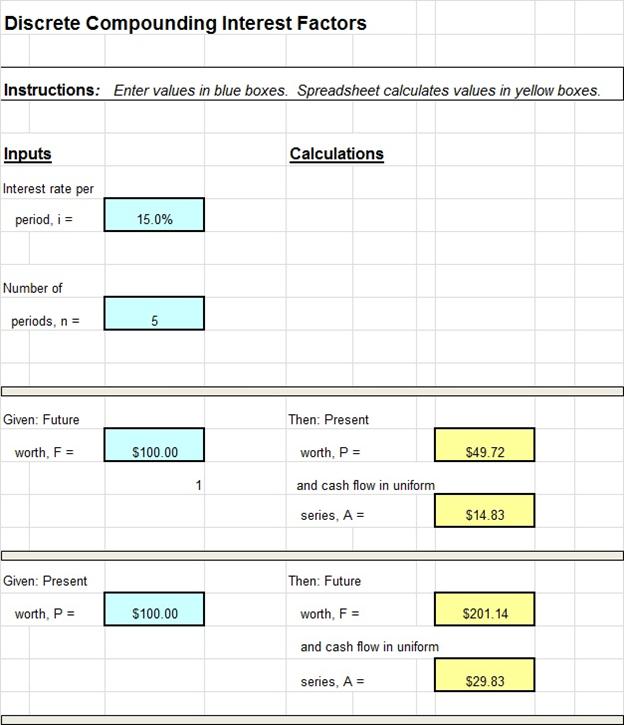
Figure 1.  Screenshot showing calculation of P and A, given F, and of F and A, given P

Continuous Compounding for Discrete Flows

The above discussion was concerned with time value calculations corresponding to interest payments made at the end of a time period, that is, discrete compounding.  If the time periods become shorter and more frequent, then the limiting case (in the sense of calculus) of continuous compounding is obtained.  It can be shown that the time value of money formulas now involve e, the base of the natural logarithms, as shown below.

Discrete flow, continuous compounding, single sum present worth factor:

P =  F (P|F r,n)

=  Fe-rn

Discrete flow, continuous compounding, sinking fund factor:

A =  F (A|F r,n)

=  F (er -1)/(ern – 1)

Discrete flow, continuous compounding, single sum future worth factor:

F =  P (F|P r,n)

=  Pern

Discrete flow, continuous compounding, capital recovery factor:

A =  P (A|P r,n)

=  P [ ern (er -1)/(ern – 1) ]

Discrete flow, continuous compounding, uniform series present worth factor:

P =  A (P|A r,n)

=  A [ (ern -1)/ ern (er – 1) ]

Discrete flow, continuous compounding, uniform series future worth factor:

F =  A (F|A r,n)

=  A [ (ern -1)/(er – 1) ]

Excel does not contain special functions for continuous compounding of discrete flows, so you must program them yourself by using the exponential function Exp( ).  Thus the availability of a specialized workbook similar to that shown in Figure 1 is even more useful here than in the discrete compounding case.

Continuous Compounding for Continuous Flows

All the above formulas are based on the assumption that cash flows occur at discrete increments at the end of time periods such as months or days.  If, instead, we assume that a total A of money flows continuously and uniformly throughout a given time period, then the result is referred to as “continuous flow.”  It can be shown that the following formulas apply in this case.

Continuous flow, continuous compounding uniform series present worth factor:

P =  A (P|A r,n)

= A [(ern – 1)/rern ]

Continuous flow, continuous compounding uniform series future worth factor:

F =  A (F|A r,n)

= A [(ern – 1)/r ]

Continuous flow, continuous compounding capital recovery factor:

A =  P (A|P r,n)

= P[ rern /(ern – 1) ]

Continuous flow, continuous compounding sinking fund factor:

A =  F (A|F r,n)

= F [ r / (ern – 1) ]

As was the case for continuous compounding of discrete flows, Excel does not contain special functions for continuous compounding of continuous flows, and so you must program them yourself by using the exponential function Exp( ).  Again the availability of a specialized workbook similar to that shown in Figure 1 is quite useful for applying these formulas.

The workbook of which the spreadsheet of Figure 1 is a part contains tabs for discrete compounding, continuous compounding for discrete flows and continuous compounding for continuous flows.   Because all formulas used in each tab are visible and can be unlocked, users possessing only a basic knowledge of Excel may easily customize the spreadsheet to meet particular needs and recurring applications.  This Excel workbook is available at low cost in our spreadsheet store.

References

1. Riggs, J.L., Bedworth, D.D., and Randhawa, S.U., Engineering Economics, 4th ed., McGraw-Hill, New York, NY (1987).

2. White, J.A., Agee, M.H., and Case, K.E., Principles of Engineering Economic Analysis, 3rd ed., Wiley, New York, NY (1989).

3. Megginson, W.L., Smart, S.B., and Lucey, B.M., Introduction to Corporate Finance, Cengage Learning, London (2008).

4. Brigham, E.F., and Ehrhardt, M.C., Financial Management, Thomson South-Western, Mason, OH (2008).


Hydraulic Jump Calculator Excel Spreadsheets

Where to Find Hydraulic Jump Calculator Excel Spreadsheets

For an Excel spreadsheets to use as an open channel flow, hydraulic jump calculatorclick here to visit our spreadsheet store.  Obtain a convenient, easy to use rectangular channel hydraulic jump calculator spreadsheet for only $14.95. Read on for information about the use of an Excel spreadsheet as a horizontal, rectangular channel hydraulic jump calculator.

Background for Hydraulic Jump Calculator

In order to discuss hydraulic jumps it’s necessary to talk about subcritical and supercritical flow.  In general subcritical flow takes place at low velocities and high flow depths, while supercritical flow occurs at high velocities and low flow depths.  For more details about critical, subcritical, and supercritical flow, see the article, “Open Channel Flow Spreadsheets – Critical Depth and Critical Slope.”  The diagram above shows supercritical flow on a steep slope, changing to subcritical flow on a mild slope.  As shown, the transition from supercritical flow to subcritical flow takes place with a hydraulic jump.  Whenever supercritical flow takes place on a slope that isn’t steep enough to maintain supercritical flow, the transition to subcritical flow will take place through the mechanism of a hydraulic jump as illustrated in the diagram.

Hydraulic Jump Calculator Parameters

Hydraulic jump calculations center on relationships among the supercritical conditions before the jump (upstream or initial conditions) and the subcritical conditions after the jump (downstream or sequent conditions).  The diagram at the left shows initial supercritical parameters and sequent subcritical parameters for a hydraulic jump.  The parameters and their typical units are summarized below:

  • y1 = the initial (upstream) depth of flow in ft for U.S. or m for S.I. units
  • V1 = the initial (upstream) liquid velocity in ft/sec for U.S. or m/s for S.I. units
  • E1 = the initial (upstream) head in ft for U.S. or m for S.I. units
  • y2 = the sequent (downstream) depth of flow in ft for U.S. or m for S.I. units
  • V2 = the sequent (downstream) liquid velocity in ft/sec for U.S. or m/s for S.I. units
  • E2 = the sequent (downstream) head in ft for U.S. or m for S.I. units
  • Q = the flow rate through the hydraulic jump in cfs for U.S. or m3/s for S.I. units
  • ΔE = the head loss across the hydraulic jump in ft for U.S. or m for S.I. units

An Excel Spreadsheet as a Hydraulic Jump Calculator

The Excel spreadsheet template shown below can be used to carry out hydraulic jump calculations.   Why bother to make these calculations by hand?  This Excel spreadsheet can calculate the sequent depth, sequent velocity, jump length, head loss across the jump, and hydraulic jump efficiency for specified initial depth, flow rate and channel width.  These spreadsheets are available in either U.S. or S.I. units at a very low cost (only $14.95 in our spreadsheet store.  These spreadsheets also have a tab for calculation of flow rate under a sluice gate and all of the equations used in the spreadsheet calculations are shown on the spreadsheets.

Note that some of the equations used in the spreadsheet calculations apply only for rectangular, horizontal channels, so the spreadsheets should be used only for channels that are at least approximately rectangular in cross-section and have a zero or very small slope.

References

1. Harlan H. Bengtson, “Hydraulic Jumps and Supercritical and Nonuniform Open Channel Flow,”  an online continuing education course for Professional Engineers.

2.  U.S. Department of Transportation, FHWA, Hydraulic Design of Energy Dissipators for Culverts and Channels, Hydraulic Engineering Circular No. 14, 3rd Ed, Chapter 6: Hydraulic Jump.

Storm Water Drain Inlet Calculations Spreadsheet

Introduction

For a storm water drain inlet calculations spreadsheet, click here to visit our spreadsheet store.  Read on for information about storm water inlet design and Excel spreadsheets to do the calculations.

Design of storm water drain inlets is basically determining the size opening needed to handle the design peak storm water runoff rate, for the particular type of inlet opening.  The links above also have spreadsheets for calculating the peak storm water runoff rate with the Rational Method equation.

Types of Pavement Drain Inlets

stormwater drain inlet calculations spreadsheet curb inlet figureThe types of pavement drain inlets in common use include curb inlets, gutter inlets and combination inlets.  A curb inlet is just an opening in the curb as shown in the image at the stormwater drain inlet calculations spreadsheet gutter inlet figureleft.  A combination inlet has both a curb opening and a grate opening in the bottom of the gutter as shown in the image at the right.  Gutter inlets typically have a grate over the opening, while curb inlets are storm water drain inlet calculations spreadsheet depressed gutter inlettypically open without a grate, as shown in the pictures.  A sketch of a depressed gutter inlet is shown at the bottom left.

Curb Inlet Image Credit: Lone Star Manhole and Structures

Combination Inlet Image Credit: Robert Lawton – Wikimedia Commons

Depressed Gutter Inlet Image Credit:  H. H. Bengtson

The Weir Model for Sizing Storm Water Drain Inlets

The openings for storm water drains can be modeled as a weir if the opening isn’t completely submerged at the design storm water runoff flow rate.  For a curb opening this would be the case if the depth of storm water at the opening is less than the height of the opening.  For a gutter opening it would occur if the design flow rate of storm water runoff enters the grate around the edges, without completely submerging the opening.

The equation used to size storm drains with unsubmerged openings is theC sharp crested weir equation:  Q = CwLd1.5, where:

  • Q = the design storm water runoff rate that must flow through the inlet in cfs for U.S. or m3/s for S.I. units.
  • Cw = a weir coefficient, which is a dimensionless constant.  Typical values are 2.3 for U.S. units and 1.27 for S.I. units.
  • L = the length of the curb opening (or the length of the the gutter opening in the direction of the storm water flow), in ft for U.S. or m for S.I. units.
  • d = the depth of storm water above the bottom of the curb opening or its depth above the gutter inlet opening in ft for U.S. or m for S.I. units.

The Orifice Model for Sizing Storm Water Drain Inlets

The storm water drain opening can be modeled as an orifice if it will be completely submerged at design flow of storm water runoff.  This would be the case for a curb opening if the water depth is more than the height of the curb opening at design storm water flow.  A gutter opening could be modeled as a weir if the gutter opening is completely submerged at the design storm water runoff rate.  The equation used for sizing storm water inlets with the orifice model is:

Q = Co A(2gde)1/2 ,  where:

  • Q = the design storm water runoff rate that must flow through the inlet in cfs for U.S. or m3/s for S.I. units.
  • Co = the orifice coefficient, which is dimensionless.  The value typically used for storm water inlet design is 0.67.
  • A = the area of the inlet opening in ft2 for U.S. or m2 for S.I. units.
  • g = the acceleration due to gravity (32.2 ft/sec2 for U.S. or 9.82 m/s2 for S.I units).
  • de = the height of storm water above the centroid of the opening in ft for U.S. or m for S.I. units.

Note that de = d – h/2, for a curb opening, where d is the depth of storm water above the bottom of the opening and h is the height of the curb opening.  For a gutter opening,  de = d, where d is the height of storm water above the gutter opening at design storm water flow.

An Excel Spreadsheet as a Storm Water Drain Inlet Design Calculator

The Excel spreadsheet template shown below can be used to calculate the required size of a curb inlet for storm water drainage, based on specified information about the design storm water runoff rate, height of the curb opening, and the height of the storm water above the bottom of the opening.  Why bother to make these calculations by hand?  This Excel spreadsheet and others with similar calculations for a gutter opening are available in either U.S. or S.I. units at a very low cost in our spreadsheet store.

storm water inlet calculations spreadsheet

References:

1. McCuen, Richard H., Hydrologic Analysis and Design, 2nd Ed, Upper Saddle River, NJ, 1998.

2. ASCE. 1992. Design and Construction of Urban Stormwater Management Systems. The Urban Water Resources Research Council of the American Society of Civil Engineers (ASCE) and the Water Environment Federation. American Society of Civil Engineers, New York, NY.

3. Texas Department of Transportation/Online Hydraulic Design Manual/Storm Drain Inlets.


Heat Exchanger Thermal Design Calculations Spreadsheet

Where to Find a Heat Exchanger Thermal Design Calculations Spreadsheet

For a double pipe heat exchanger thermal design calculations spreadsheetclick here to visit our spreadsheet store.  Read on for information about the use of a heat exchanger design thermal design calculations spreadsheet for a double pipe heat exchanger.

The Basic Equation for a Heat Exchanger Thermal Design Calculations Spreadsheet

The basic heat exchanger design equation is:  Q = U A ΔTlm,    where:

  • Q = the rate of heat transfer between the two fluids in the heat exchanger in But/hr (kJ/hr for S.I. units)
  • U is the overall heat transfer coefficient in Btu/hr-ft2oF  (kJ/hr-m2-K for S.I. units)
  • A is the heat transfer surface area in ft2 (m2 for S.I. units)
  • ΔTlm is the log mean temperature difference in oF,  (K for S.I units)  calculated from the inlet and outlet temperatures of both fluids.

For a heat exchanger thermal design calculations spreadsheet, the heat exchanger equation can be used to calculate the required heat exchanger area for known or estimated values of the other three parameters, Q, U, and ΔTlm.  Each of those parameters will be discussed briefly in the next three sections.

The Log Mean Temperature Difference, ΔTlm , for a Heat Exchanger Design Spreadsheet

Equation for heat exchanger thermal design calculations spreadsheetThe driving force for a heat transfer process is always a temperature difference. For heat exchangers, there are always two fluids involved, and the temperatures of both are changing as they pass through the heat exchanger.  Thus some type of average temperature difference is needed.  Many heat transfer textbooks (e.g. ref #1 below) show double pipe heat exchanger diagram for heat exchanger thermal design calculations spreadsheetthat the log mean temperature difference is the appropriate average temperature difference to use for heat exchanger design calculations.  The definition of the log mean temperature difference is shown in the figure above.  The meanings of the four temperatures in the log mean temperature difference equation are rather self explanatory as shown in the diagram of a counterflow double pipe heat exchanger at the right.

The Heat Transfer Rate, Q, for a Heat Exchanger Thermal Design Calculations Spreadsheet

In order to use the heat exchanger design equation to calculate a required heat transfer area,  a value is needed for the heat transfer rate, Q.  This rate of heat flow can be calculated if the flow rate of one of the fluids is known along with its specific heat and the required temperature change for that fluid. The equation to be used is shown below for both the hot fluid and the cold fluid:

Q = mH CpH (THin – THout) = mC CpC (TCout – TCin), where

  • mH is the mass flow rate of the hot fluid in slugs/hr (kg/hr for S.I. units).
  • CpH is the specific heat of the hot fluid in Btu/slug-oF (kJ/kg-K for S.I. units).
  • mC is the mass flow rate of cold fluid in slugs/hr (kg/hr for S.I. units).
  • CpC is the specific heat of the cold fluid in Btu/slug-oF (kJ/kg-K for S.I. units).
  • The temperatures (THin, THout, TCout, & TCin) are the hot and cold fluid temperatures going in and out of the heat exchanger, as shown in the diagram above.  They should be in oF for U.S. or K for S.I. units.

The heat transfer rate, Q, can be calculated in a preliminary heat exchanger design spreadsheet if the flow rate, heat capacity and temperature change are known for either the hot fluid or the cold fluid. Then one unknown parameter can be calculated for the other fluid.  (e.g. the flow rate, the inlet temperature, or the outlet temperature.)

The Overall Heat Transfer Coefficient, U, for a Heat Exchanger Design Spreadsheet

The overall heat transfer coefficient, U, depends on the convection coefficient inside the pipe or tube, the convection coefficient on the outside of the pipe or tube, and the thermal conductivity of the pipe wall.  See the article, Forced Convection Heat Transfer Coefficient Calculations, for information about calculating the heat transfer coefficients and click here to visit our spreadsheet store, for spreadsheets to calculate the inside and outside convection coefficients and to calculate the overall heat transfer coefficient.

A Heat Exchanger Thermal Design Calculations Spreadsheet

The screenshot below shows a heat exchanger thermal design calculations spreadsheet that can be used to carry out thermal design of a double pipe heat exchanger.  The image shows only the beginning of the calculations.  The rest of the spreadsheet will calculate the length of pipe needed, the length of each pass for a selected number of 180 degree bends, and the pressure drop through the inside of the pipe.  Why bother to make these calculations by hand?  This Excel spreadsheet is available in either U.S. or S.I. units at a very low cost at in our spreadsheet store.

Heat Exchanger Thermal Design Calculations Spreadsheet

References

1. Kuppan, T., Heat Exchanger Design Handbook, CRC Press, 2000.

2. Kakac, S. and Liu, H., Heat Exchangers: Selection, Rating and Thermal Design, CRC Press, 2002.

3. Bengtson, H., Fundamentals of Heat Exchangers, an online, continuing education course for PDH credit.

4. Bengtson, H., Thermal Design of a Double Pipe Heat Exchanger, and online blog article.

Critical Depth Open Channel Flow Spreadsheet

Where to Find a Critical Depth Open Channel Flow Spreadsheet

To obtain a critical depth open channel flow spreadsheet for calculating critical depth and/or critical slope for open channel flow, click here to visit our spreadsheet store.  Read on for information about the use of a critical depth open channel flow spreadsheet for critical depth and critical slope calculations.

The Froude Number and Critical, Subcritical and Supercritical Flow

Any particular example of open channel flow will be critical, subcritical, or supercritical flow.  In general, supercritical flow is characterized by high liquid velocity and shallow flow, while subcritical flow is characterized by low liquid velocity and relatively deep flow.  Critical flow is the dividing line flow condition between subcritical and supercritical flow.

The Froude number is a dimensionless number for open channel flow that provides information on whether a given flow is subcritical, supercritical or critical flow.  The Froude number is defined to be:  Fr = V/(gL)1/2 , where V is the average velocity, g is the acceleration due to gravity, and L is a characteristic length for the particular type of open channel flow.  For flow in a rectangular channel:  Fr = V/(gy)1/2 ,   where y is the depth of flow.  For flow in an open channel with a shape other than rectangular:  Fr = V/[g(A/B)]1/2 , where A is the cross-sectional area of flow, and B is the surface width.

The value of the Froude number for a particular open channel flow situation gives the following information:

  • For Fr < 1, the flow is subcritical
  • For Fr = 1, the flow is critical
  • For Fr > 1, the flow is supercritical

Calculation of Critical Depth

It is sometimes necessary to know the critical depth for a particular open channel flow situation.  This type of calculation can be done using the fact that Fr = 1 for critical flow.  It is quite straightforward for flow in a rectangular channel and a bit more difficult, but still manageable for flow in a non-rectangular channel.

For flow in a rectangular channel (using subscript c for critical flow conditions), Fr = 1 becomes:   Vc/(gyc)1/2 = 1.  Substituting Vc =  Q/Ac =  Q/byc and  q = Q/b  (where b = the width of the rectangular channel), and solving for yc gives the following equation for critical depth: yc =  (q2/g)1/3.   Thus, the critical depth can be calculated for a specified flow rate and rectangular channel width.

For flow in a trapezoidal channel, Fr = 1 becomes:  Vc/[g(A/B)c]1/2 = 1.  Substituting the equation above for Vc together with Ac =  yc(b + zyc)    and   Bc =  b  +  zyc2 leads to the following equation, which can be solved by an iterative process to find the critical depth:

Critical Depth Open Channel Flow Spreadsheet Formula1

Calculation of Critical Slope

After the critical depth, yc ,  has been determined, the critical slope, Sc , can be calculate using the Manning equation if the Manning roughness coefficient, n, is known.  The Manning equation can be rearranged as follows for this calculation:

Critical Depth Open Channel Flow Spreadsheet Formula2Note that Rhc , the critical hydraulic radius, is given by:

Rhc =  Ac/Pc,  where Pc =  b  +  2yc(1 + z2)1/2

Note that calculation of the critical slope is the same for a rectangular channel or a trapezoidal channel, after the critical depth has been determined.  The Manning equation is a dimensional equation, in which the following units must be used:  Q is in cfs, Ac is in ft2, Rhc is in ft, and Sc and n are dimensionless.

Calculations in S.I. Units

The equations for calculation of critical depth are the same for either U.S. or S.I. units.  All of the equations are dimensionally consistent, so it is just necessary to be sure that an internally consistent set of units is used.  For calculation of the critical slope, the S.I. version of the Manning equation must be used, giving:

Critical Depth Open Channel Flow Spreadsheet Formula4In this equation, the following units must be used:  Q is in m3/s, Ac is in m2, Rhc is in m, and Sc and n are dimensionless.

A Critical Depth Open Channel Flow Spreadsheet Screenshot

The critical depth open channel flow spreadsheet template shown below can be used to calculate the critical depth and critical slope for a rectangular channel with specified flow rate, bottom width, and Manning roughness coefficient.  Why bother to make these calculations by hand?  This Excel spreadsheet and others with similar calculations for a trapezoidal channel are available in either U.S. or S.I. units at a very low cost in our spreadsheet store.

Critical Depth Open Channel Flow Spreadsheet Screenshot

References

1. Munson, B. R., Young, D. F., & Okiishi, T. H., Fundamentals of Fluid Mechanics, 4th Ed., New York: John Wiley and Sons, Inc, 2002.

2. Chow, V. T., Open Channel Hydraulics, New York: McGraw-Hill, 1959.

3. Bengtson, Harlan H. Open Channel Flow II – Hydraulic Jumps and Supercritical and Nonuniform FlowAn online, continuing education course for PDH credit.


Using Superposition in a Continuous Beam Analysis Spreadsheet

Where to Find a Continuous Beam Analysis Spreadsheet

To obtain a continuous beam analysis spreadsheet, Click Here to go to our spreadsheet store.    Also, check out our Free Android App for analyzing a simply supported beam with a concentrated load.  Read on for information about performing  continuous beam analyses via superposition and how Excel spreadsheets can be used in this procedure.

The equation giving the deflection of a beam with a complicated loading can often be found relatively easily by superposing two or more deflection equations corresponding to simple loadings.  Superposition can be used, however, only if the beam deflections are small, say less than 1/500-th of the beam span.  Fortunately the vast majority of beams designed by structural and mechanical engineers involve deflections this small or smaller, and thus superposition is applicable to a wide range of practical problems.

Background on Superposition in a Continuous Beam Analysis Spreadsheet

The theoretical justification for superposition is straightforward.  Consider the differential equation for beam deflection, y(x)

in which w(x) is the load acting on the beam, E isthe elastic modulus of the beam material, I is the moment of inertia of the cross section, and x is a horizontal coordinate, measured from the left end and locating points on the beam.  The deflection function y(x) must satisfy Eq. 1 and also the boundary conditions.  For example, for a beam fixed at both ends, the boundary conditions would be

in which L is the length of the beam.

Now suppose that a load w1(x) acts on the beam.  Then the deflection y1(x) of the beam is governed by Eq.1:

Next, remove the load w1(x) and apply a different load, w2(x).  Then the deflection y2(x) of the beam is also governed by Eq.1:

Adding Eqs. 3 and 4 and defining a new function, y3(x) ≡ y1(x) + y2(x), gives

In words, y3(x) satisfies the differential equation for a beam subjected to the combined loading, w1(x) plus w2(x), and, furthermore, y3(x) can be found by simply adding the deflection equations corresponding to w1(x) and w2(x) acting alone (Note that boundary conditions, such as Eq. 2, also are satisfied after superposition).

So why bother with superposition?  Why not just solve Eq. 5 directly for y3(x)?  Answer: Superposition is in fact not worth bothering about, unless tabulated solutions exist for y1(x) and y2(x).  Because if someone else has already solved the differential equations for y1(x) and y2(x) (and the solutions are available to you, typically through a published table of solutions) then all you have to do is add their results—you completely avoid the time-consuming, error-prone process of solving the differential equation for y3(x).

Example Calculations with Beam Formulas

As an illustration, consider the beam shown in the figure below.

For concreteness, let a1 = 2 m, a2 = 3 m, L = 12 m, P1 = 10 kN, P2 = 14 kN, E = 200 GPa, and I = 600 000 cm­4.

The general result for a single load is given by equation (6) below, which is found in all tables of beam deflection formulas:

The deflection equation is

This equation can be used to give the deflection equation y(x) for our two-load problem through superposition

y(x)  =  yo(x, 10 kN, 2 m)  +  yo(x, 14 kN, 9 m)                                                                      (7)

That is, we apply Eq. 6 twice, once for the 10-kN load acting a = 2 m from the left end, and once for the 14-kN load acting a = 12 m − 3 m = 9 m from the left end.

The forms of Eqs. 6 and 7 are well-suited for implementation in a spreadsheet.  We only have to program a single formula (with an “If” statement) representing Eq. 6, and then we can superpose  the results of that formula once for each concentrated load acting on the beam—no matter how many loads act or where they act.  The same superposition approach can be used to calculate the shear and moment diagrams.Obviously, a similar approach can be used for other tabulated solutions, such as those corresponding to a concentrated moment or distributed load acting on the beam.

Screenshot for Continuous Beam Analysis Spreadsheet Calculations

The screenshot image below shows an Excel spreadsheet to calculate the shear and moment diagrams and deflections for two concentrated loads acting on a simply-supported beam.  Note that only the absolute minimum of information is required: the magnitude and location of the loads and the values of E and I.  No nodal numbering, element numbering, boundary condition specification, output specification, and load type must be entered.


The workbook of which this spreadsheet is a part contains tabs for one and two concentrated forces, one and twoconcentrated moments, one and two linearly varying distributed loads, and a combination of all three types of loadings.  The procedure to extend the analysis to other load cases is also presented in a tab.  Because all formulas used in each tab are visible and can be unlocked, userspossessing only a basic knowledge of Excel may easily customize the spreadsheet to meet particular needs and recurrent applications.  This Excel workbook and additional workbooksfor other boundary conditions are available in either U.S. or S.I. units at low cost in our spreadsheet store.

References

1. Manual of Steel Construction, Load & Resistance Factor Design, Volume I, Structural Members, Specifications & Codes, 2nd Edition, American Institute of Steel Construction, Chicago, IL, American Institute of Steel Construction (1994).

2. Egor P. Popov, Engineering Mechanics of Solids, 2nd Edition, Prentice Hall, New York, NY (1998).

3. Rossow, Mark, “Structural Analysis of Beams Spreadsheets,”  an online blog article