Where to Find a Pipe Flow-Friction Factor Calculator Excel Spreadsheet
For a pipe flow-friction factor calculator Excel Spreadsheet, click here to visit our spreadsheet store. Why read values from a Moody diagram, make iterative calculations to get friction factor, or use online calculators, when you can get a pipe flow-friction factor calculator Excel Spreadsheet for only $19.95? Read on for information about the Darcy Weisbach equation and its use in an Excel spreadsheet as a friction factor/pipe flow calculator.
Excel spreadsheets are very convenient for Darcy Weisbach equation/pipe flow calculations, such as frictional pressure drop calculation or use of a friction factor calculator, at least in part because some of the calculations require iterative solutions. The Darcy Weisbach equation is applicable to pressure flow in pipes, rather than gravity flow (as in sewer pipes), which is handled by open channel flow equations like the Manning equation. The Darcy Weisbach equation provides the relationship among the following parameters: pipe diameter and length, pipe flow rate, and frictional pressure drop or head loss. Any one of these can be calculated if the others are known along with the density and viscosity of the fluid.
A Friction Factor Calculator and the Darcy Weisbach Equation
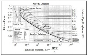 The Darcy Weisbach equation is hL= f(L/D)(V2/2g), with the parameters in the equation as follows: hLis the frictional head loss for flow of a fluid at average velocity, V, through a pipe of length,L, and diameter,D. The Reynolds number for the flow (Re) and the relative roughness of the pipe (e/D) are needed to get a value for the friction factor,f. The Moody Diagram at the right shows the nature of the dependence of the friction factor, f, on Re and e/D.
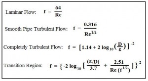 Equations for f as a function of Re and e/D would be more convenient than a graph like the Moody Diagram for use with Excel spreadsheets making pipe flow calculations with the Darcy Weisbach equation. Such equations are shown in the box at the left, giving the relationships between Moody friction factor and Re & e/D for four different portions of the Moody diagram. The four portions of the Moody diagram are:
- laminar flow(Re < 2100 – the straight line at the left side of the Moody
- smooth pipe turbulent flow(the dark curve labeled “smooth pipe” in the Moody diagram – f is a function of Re only in this region)
- completely turbulent region(the portion of the diagram above and to the right of the dashed line labeled “complete turbulence” – f is a function of e/D only in this region)
- transition region(the portion of the diagram between the “smooth pipe” solid line and the “complete turbulence” dashed line – f is a function of both Re and e/D in this region and this is not an explicit equation for f)
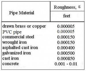
The table above right gives pipe roughness values for several common pipe materials. These can be used to calculate the pipe roughness ratio, e/D.
For a low cost Moody friction factor calculator download, that will calculate f for Reynolds number above 2100, see: www.engineeringexceltemplates.com
Frictional Head Loss and Frictional Pressure Drop Calculation
After using the Moody friction factor calculator to get a value for the friction factor, f, frictional head loss calculation is quite straightforward if the pipe length & diameter and average flow velocity are known. You simply need to substitute values for L, D, V, and f into the Darcy Weisbach equation [hL= f(L/D)(V2/2g) ]. The Darcy Weisbach equation is a dimensionally consistent equation, so any consistent set of units can be used. For U.S. units, hL, L, and D are typically in ft, V is in ft/sec, and g is 32.2 ft/sec2. For S.I. units, hL, L and D are typically in m, V is in m/s, and g is 9.81 m/s2. If volumetric flow rate, Q, is known rather than average velocity, V, then V can be calculated from:
Frictional pressure drop calculation from frictional head loss is done through the equation:
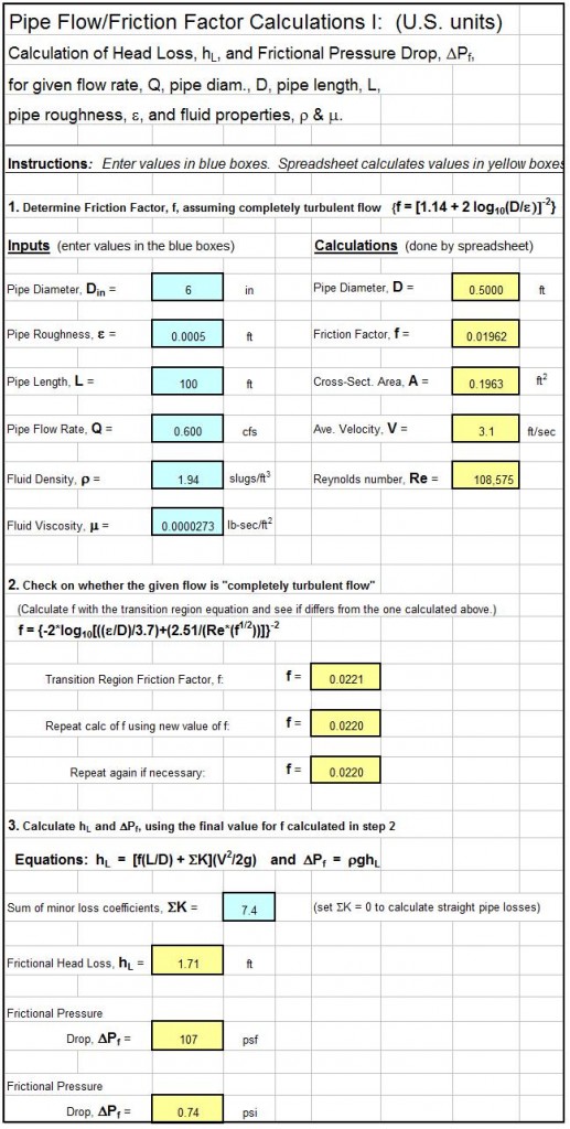
A Screenshot for a Pipe Flow-Friction Factor Calculator Excel Spreadsheet
The Excel spreadsheet screenshot below shows a pipe flow-friction factor calculator excel spreadsheet that is available as part of the “Pipe Flow-Friction Factor Calculation Package,” at our spreadsheet store in either U.S. or S.I. units at a very low cost (only $16.95). This spreadsheet package has three worksheets: one to calculate frictional head loss and pressure drop for known pipe diameter, length & material and flow rate; one to serve as a pipe flow rate calculator for known head loss/pressure drop, and pipe diameter, length & material; and one to calculate required pipe diameter for known head loss/pressure drop, flow rate, and pipe length & material.
1. Munson, B. R., Young, D. F., & Okiishi, T. H., Fundamentals of Fluid Mechanics, 4th Ed., New York: John Wiley and Sons, Inc, 2002.
2. Darcy Weisbach equation history – http://biosystems.okstate.edu/darcy/DarcyWeisbach/Darcy-WeisbachHistory.htm
3. Source for pipe roughness values – http://www.efunda.com/formulae/fluids/roughness.cfm
4. Bengtson, H.H., Pipe Flow/Friction Factor Calculations with Excel, and online continuing education course for Professional Engineers.
5. Bengtson, Harlan H., “Pipe Flow Friction Factor Calculations with Spreadsheets,” available as an Amazon Kindle e-book and as a paperback.
6. Bengtson, Harlan H., “Pipe Flow Calculations with the Darcy Weisbach Equation“, an online blog article


