Broad Crested Weir Calculations Spreadsheet


Where to Find a Broad Crested Weir Calculations Spreadsheet

To obtain a Broad Crested Calculations Spreadsheetclick here to visit our spreadsheet store.  This Excel spreadsheet is intended for calculating the flow rate over the weir for free flow over the weir or for submerged flow.  . You can buy a convenient broad crested weir calculations spreadsheet for a very reasonable price.  It is available in either U.S. units or S.I. units.  Read on for background information about a broad crested weir calculations spreadsheet

Background for a Broad Crested Weir Calculations Spreadsheet

Figure 1, below shows a longitudinal section of a broad crested weir with free flow over the weir.

Broad crested weir calculations spreadsheet
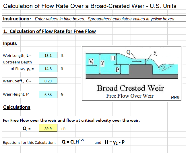
Figure 1. Longitudinal Section of a Broad Crested Weir with Free Flow over the Weir

The flow over a broad crested weir is referred to as free flow if the depth of water flowing immediately downstream of the weir is lower than the weir crest (the top of the weir), as shown in Figure 1.  The broad crested weir calculations spreadsheet being described here can calculate the flow rate over the weir for user specified values of the depth of flow upstream of the weir, y1, the length of the weir crest, L, (typically equal to the width of channel in which the broad crested weir is placed), and the value to be used for the weir coefficient, C.  The equation used for this calculations is:

broad crested weir calculations spreadsheetA similar calculation can be made for submerged flow over the broad crested weir, in which the depth of flow immediately downstream of the weir is greater than the height of the weir.  Submerged flow over a broad crested weir is shown in Figure 2 below.

broad crested weir calculations spreadsheetAlso the required upstream head above the weir crest can be calculated for a given flow rate over the weir for either free flow over the weir or submerged flow

Example Broad Crested Weir Calculations Spreadsheet

An example broad crested weir calculations spreadsheet is partially shown in the image below.  .  This Excel spreadsheet can be used to calculate the flow rate over the weir or to calculate the required upstream head over the weir for a given flow rate. These calculations can be made for free flow over the weir or for submerged flow over the broad crested weir.  This Excel spreadsheet, as well as others for open channel flow measurement calculations, is available in either U.S. or S.I. units for a very reasonable price in our spreadsheet store.

broad crested weir calculation spreadsheet screenshot

References:

1. Federal Highway Administration,  Publication No. FHWA-HIF-12-018, Hydraulic Design Series Number 7, Hydraulic Design of Safe Bridges, April 2012.2

2. Bengtson, Harlan H.,  “ Spreadsheet for Broad Crested Weir Calculations,” an online blog article.

Partially Contracted V-Notch Weir Excel Spreadsheets

Where to Find a Partially Contracted V-Notch Weir Excel Spreadsheet

To obtain a Partially Contracted V-notch weir Excel spreadsheet for , click here to visit our spreadsheet store. Why use online calculators or hand calculations when you can buy a partially contracted V-notch weir spreadsheet for only $11.95.  Read on for information about Excel spreadsheets that can be used as v-notch weir open channel flow calculators for partially contracted flow.

For background on fully contracted v notch weir calculations, see the article, “V-Notch Weir Calculator Excel Spreadsheet.”   That article gives general information about V notch weirs and equations and conditions required for fully contracted v notch weir calculations.

Partially Contracted V Notch Weir Calculations for a 90o Notch Angle

Partially contracted v-notch weir excel spreadsheet diagram

The equation shown below is recommended by the U.S. Dept. of the Interior, Bureau of Reclamation in their Water Measurement Manual (ref #1 below) for calculations with a partially contracted, 90o, v notch, sharp crested weir with free flow conditions and 0.4 ft < H < 2 ft (0.05 m < H < 0.38 m).

In U. S. units:  Q = 4.28H2.48, where Q is discharge in cfs and H is head over the weir in ft.

In S.I. units:  Q = 1.36H2.48, where Q is discharge in  m3/s and H is head over the weir in m.

The conditions for the v notch weir to be fully contracted are:

H/P < 1.2,    H/B < 0.4,    P > 0.33 ft (0.1 m),   B > 2 ft (0.6 m)

The diagram above shows the parameters H, P, θ and B for a v notch weir as used for open channel flow rate measurement in a partially contracted v-notch weir excel spreadsheet.

Screenshot of a Partially Contracted V Notch Weir Excel Spreadsheet

The screenshot below shows a partially contracted v notch weir excel spreadsheet for making 90o, partially contracted v-notch weir calculations in U.S. units.  Based on specified values for H, P, & B (and a value for Ce from a graph on the spreadsheet), the spreadsheet checks on whether the required conditions for partially contracted flow are met and then calculates the flow rate, Q.  This Excel spreadsheet and others for v notch weir calculations are available in either U.S. or S.I. units at a very low cost (only $11.95)  in our spreadsheet store.

partially contracted v-notch weir spreadsheet screenshot

References:

1. U.S. Dept. of the Interior, Bureau of Reclamation, 2001 revised, 1997 third edition, Water Measurement Manual, available for online use or download at: http://www.usbr.gov/pmts/hydraulics_lab/pubs/wmm/index.htm.

2. Bengtson, Harlan H., “Sharp Crested Weirs for Open Channel Flow Measurement,” an Amazon Kindle ebook

3. Bengtson, Harlan H., Open Channel Flow III – Sharp Crested Weirs, an online continuing education course for PDH credit, http://www.online-pdh.com/engcourses/course/view.php?id=87

4. Munson, B. R., Young, D. F., & Okiishi, T. H., Fundamentals of Fluid Mechanics, 4th Ed., New York: John Wiley and Sons, Inc, 2002.

Proportional Sutro Weir Design Calculation Excel Spreadsheet

Where to get a Proportional Sutro Weir Design Calculation Excel Spreadsheet

For a proportional sutro weir design calculation Excel spreadsheet in either U.S. or S.I. units, click here to visit our spreadsheet store.  Obtain convenient, easy to use spreadsheets for proportional sutro weir design calculations at reasonable prices. Read on for information about the use of a proportional sutro weir design calculation Excel spreadsheet.

Principles of a Proportional Sutro Weir Design Calculation Excel Spreadsheet

For the commonly used rectangular weir or V-notch weir, the flow rate over the weir Diagram for proportional sutro weir design calculation excel spreadsheetincreases as the head over the weir increases, but the flow rate increases at a faster rate than the head over the weir.  For some applications, it is desirable for the flow rate over a weir to be proportional to the head over the weir.  The sutro weir, also known as a proportional weir accomplishes this by having the width of the opening above the weir crest decrease with increasing head over the weir crest as shown in the diagram of a sutro weir at the right.  Equations that can be used for proportional sutro weir design are discussed in the next section.

Equations for Proportional Sutro Weir Design Calculation Excel Spreadsheet

Equations for the base width and base height of a sutro weir are as follows:

base height equation for proportional sutro weir design calculation Excel spreadsheet

base width equation for proportional sutro weir design calculation Excel spreadsheet

  • Wb  =  base width in ft (m for S.I. units)
  • Hb  =  base height in ft (m for S.I. units)
  • Hc  =  max height or curved portion of weir in ft (m for S.I. units)
  • Qmax  =  design maximum flow over the weir in cfs (m3/s for S.I. units)
  • Qmin  =  design minimum flow over the weir in cfs (m3/s for S.I. units)
  • g = acceleration of gravity = 32.17 ft/s/s (9.81 m/s/s for S.I. units)

The equation for the curved portion of a proportional sutro weir is:

Curve Equation for proportional sutro weir design calculation Excel spreadsheet

X and Z are position parameters as shown in the diagram above.  They will have the same units as Wb .

A Screenshot for a Proportional Sutro Weir Design Calculation Excel Spreadsheet

For a proportional sutro weir design calculation Excel spreadsheet with calculations in S.I. or U.S. units, or for other spreadsheets for open channel flow measurement calculations, see: www.engineeringexceltemplates.com

The Excel spreadsheet screenshot below shows part of a spreadsheet for proportional sutro weir design calculations, available  at our spreadsheet store in either U.S. or S.I. units at a very reasonable price.

 Screenshot of Proportional Sutro Weir Design Calculation Excel Spreadsheet

Reference

1, U.S. DOT, Fed Highway Admin, Urban Design Manual, Circular No. 22, 2nd Ed. 2001  (Publ. No. FHWA-NHI-010021-HEC-22)

2. Bengtson, Harlan H., Proportional Weir Design Equations,” an online blog article

Sharp Crested Rectangular Weir Flow Calculator Spreadsheet

Where to Find a Rectangular Weir Flow Calculator Spreadsheet

For a rectangular weir flow calculator spreadsheet, click here to visit our spreadsheet store. Obtain a convenient, easy to use spreadsheet to use as a rectangular weir flow calculator at a reasonable price.   Read on for information about Excel spreadsheets that can be used as contracted rectangular weir open channel flow calculators.

The following section, which gives background on sharp crested rectangular weirs in general, also appears in the companion article, “Suppressed Rectangular Weir Calculations with an Excel Spreadsheet

Background on Sharp Crested Rectangular Weirs in General

The picture at the left shows a rectangular weir measuring open channel flow rate in a natural channel.  The diagram below right shows a longitudinal cross-section of a sharp crested weir, with some of the terminology and parameters often used for sharp crested weirs included on the diagram.

The weir crest is the top of the weir. For a rectangular weir it is the straight, levelsharp crested weir parameters for rectangular weir flow calculatorbottom of the rectangular opening through which water flows over the weir. The term nappe is used for the sheet of water flowing over the weir. The equations for calculating flow rate over a weir in this article require free flow, which takes place when there is air under the nappe. The drawdown is shown in the diagram as the decrease in water level going over the weir due to the acceleration of the water.  The head over the weir is shown as H in the diagram; the height of the weir crest is shown as P; and the open channel flow rate in the open channel (and over the weir) is shown as Q.

Image Credits:  Rectangular, Sharp-Crested Weir: flowmeterdirectory.co.uk

Sharp Crested Weir Parameters:  H. H. Bengtson, Ref #2

The Francis Equation for a Rectangular Weir Flow Calculator

contracted rectangular weir diagram for rectangular weir flow calculatorA contracted rectangular weir is one for which the weir extends across only part of the channel, so that the length of the weir, L, is different from as the width of the channel.  The picture at the left shows a contracteded rectangular weir being used to measure the flow of water in a triangular open channel.  The diagram below right shows some of the key parameters used in contracted rectangular weir flow rate calculations. contracted rectangular weir diagram - rectangular weir flow calculator Specifically, the height of the weir crest, P, the head over the weir, H, the weir length, L, and the channel width, B, are shown on the diagram of a contracted rectangular weir in a rectangular channel.  The U.S. Bureau of Reclamation, in their Water Measurement Manual (Ref #1 below), recommend the use of the Francis equation (shown below) for completely contracted rectangular weirs, subject to the condition that  H/L < 0.33,  B – L > 4 Hmax,  and > 2Hmax.

For U.S. units:  Q = 3.33(L – 0.2H)H3/2,  where

  • Q is the water flow rate in ft3/sec,
  • L is the length of the weir in ft,
  • H is the head over the weir in ft,
  • B is the width of the channel in ft, and
  • Hmax is the maximum expected head over the weir in ft.

For S.I. units:  Q = 1.84(L – 0.2H)H3/2, where

  • Q is the water flow rate in m3/sec,
  • L is the length of the weir in m, and
  • H is the head over the weir in m.
  • B is the width of the channel in m, and
  • Hmax is the maximum expected head over the weir in m.

Image Credits:  Contracted Rectangular Weir picture: Food and Agricultural Organization of the United Nations.

Contracted Rectangular Weir Diagram – Bengtson, Harlan H.

The Kindsvater-Carter Formula for a Rectangular Weir Flow Calculator

If any of the three required conditions given in the previous section are not met, then the more general Kindsvater- Carter Equation, shown below should be used.

U.S. units: Q  =  Ce(2/3)[(2g)1/2](L + kb)(H + 0.003)3/2

S.I. units: Q  =  Ce(2/3)[(2g)1/2](L + kb)(H + 0.001)3/2

Ce is a function of L/B and H/P, while  kb is a function of L/B.  There are graphs, tables and equations available for obtaining values for Ce and kb for specified values of L/B and H/P. The equations given below were prepared from information in Reference #3 at the end of the article.

Ce is dimensionless, so the equation for Ce is as a function of L/B and H/P is the same for both S.I. and U.S. units and is as follows:

Ce = α(H/P) + β, where  β = 0.58382 + 0.016218(L/B), and

α = [-0.0015931 + 0.010283(L/B)]/[1 – 1.76542(L/B) + 0.870017(L/B)2]

The equation for kb as a function of L/B has different constants for S.I. and U.S. units.  The two versions of the equation for kb are as follows:

U.S. units: for 0 < L/B < 0.35:   kb = 0.007539 + 0.001575(L/B)  – (kb is in ft)

for 0.35 < L/B < 1.0:  kb = -0.34806(L/B)4 + 0.63057(L/B)3 – 0.37457(L/B)2 + 0.09246(L/B) – 0.000197 (kb is in ft)

S.I. units: for 0 < L/B < 0.35:   kb = 0.002298 + 0.00048(L/B) (kb is in m)

for 0.35 < L/B < 1.0:  kb = -0.10609(L/B)4 + 0.1922(L/B)3 – 0.11417(L/B)2 + 0.028182(L/B) – 0.00006 – (kb is in m)

Note that if H/L < 0.33,  B – L > 4 Hmax,  and P > 2Hmax, then the Francis Equation and the Kindsvater-Carter Equation will give nearly the same value for Q.  As conditions diverge more and more from the requirements, the calculations from the two equations will diverge more and more.  In these cases the value calculated by the Kindsvater-Carter formula should be used.

An Excel Spreadsheet as a Contracted Rectangular Weir Flow Calculator

The Excel spreadsheet template shown below can be used as a contracted rectangular weir flow calculator, using both the Francis equation and the Kindsvater-Carter equation.  Only four input values are needed.  They are the height of the weir crest above the channel invert, P; the width of the channel, B; the weir length L; and the measured head over the weir, H. With these four input values, the Excel formulas will calculate the parameters needed and check on whether the conditions required for use of the Francis equation are met. If the conditions are all met, then the value of Q calculated with the Francis equation can be used.  If any of the conditions aren’t met, then the value of Q calculated with the Kindsvater-Carter formula should be chosen.  This Excel spreadsheet and others for suppressed and contracted rectangular weir calculations are available in either U.S. or S.I. units at a very low cost in our spreadsheet store.

Rectangular weir flow calculator spreadsheet screenshot

References

1. U.S. Dept. of the Interior, Bureau of Reclamation, 2001 revised, 1997, 3rd ed,  Water Measurement Manual

2. Bengtson, H.H., Sharp Crested Weirs for Open Channel Flow Measurement, an Amazon Kindle ebook.

3. Bengtson, H.H., Open Channel Flow Measurement – Weirs and Flumes, An online continuing education course for PDH credit for Professional Engineers

4. Bengtson, H. H., Sharp-Crested Weirs for Open Channel Flow Measurement, An online continuing education course for PDH credit for Professional Engineers.

5. Merkley, Gary P., Weirs for Flow Measurement Open Course Ware, Utah State University.


Suppressed Rectangular Weir Calculations with Excel Spreadsheets

Introduction to Suppressed Rectangular Weir Calculations

For an Excel spreadsheet to make suppressed rectangular weir flow calculations, click here to visit our spreadsheet store.  Read on for information about Excel spreadsheets that can be used as suppressed rectangular weir open channel flow calculators.

As shown in the diagrams and pictures below, the rectangular refers the the shape of the water cross-section as it goes over a sharp crested rectangular weir, which consists of a plate placed in an open channel so that the water is forced to flow through the rectangular open in the weir plate.  It can be used for open channel flow rate measurement, by measuring the height of water above the weir crest (the straight, level top of the weir opening), which can then be used to calculate the water flow rate over the weir.

Background on Sharp Crested Rectangular Weir Calculations in General

suppressed rectangular weir calculations imageThe picture at the left shows a rectangular weir measuring open channel flow rate in a natural channel.  The diagram below right shows a longitudinal cross-section of a sharp crested weir, with some of the terminology and parameters often used for sharp crested weirs included on the diagram.

The weir crest is the top of the weir. For a rectangular weir it is the straight, level suppressed rectangular wier calculatons longitudinal sectionbottom of the rectangular opening through which water flows over the weir. The term nappe is used for the sheet of water flowing over the weir. The equations for calculating flow rate over a weir in this article require free flow, which takes place when there is air under the nappe. The drawdown is shown in the diagram as the decrease in water level going over the weir due to the acceleration of the water.  The head over the weir is shown as H in the diagram; the height of the weir crest is shown as P; and the open channel flow rate in the open channel (and over the weir) is shown as Q.

Image Credits:  Rectangular, Sharp-Crested Weir: flowmeterdirectory.co.uk

Sharp Crested Weir Parameters:  H. H. Bengtson, Ref #2

The Francis Equation for Suppressed Rectangular Weir Calculations

suppressed rectangular weir calculations pictureA suppressed rectangular weir is one for which the weir extends across the entire channel, so that the length of the weir, L, is the same as the width of the channel, B.  The picture at the left shows a suppressed rectangular weir being used to measure the flow of water in an open channel.  The diagram below right shows some of the key parameters used in suppressed rectangular weir flow rate calculations.  Specifically, the suppressed rectangular weir imageheight of the weir crest, P, the head over the weir, H, and the weir length, L (equal to channel width, B) are shown on the diagram.  The U.S. Bureau of Reclamation, in their Water Measurement Manual (Ref #1 below), recommend the use of the Francis equation (shown below) for suppressed rectangular weirs, subject to the condition that  H/P < 0.33 and H/B < 0.33:

For U.S. units: Q = 3.33 B H3/2, where

  • Q is the water flow rate in ft3/sec,
  • B is the length of the weir (and the channel width) in ft, and
  • H is the head over the weir in ft.

For S.I. units:  Q = 1.84 B H3/2, where

  • Q is the water flow rate in m3/sec,
  • B is the length of the weir (and the channel width) in m, and
  • H is the head over the weir in m.

The same condition for H/P and H/B apply.

Image Credits:  Suppressed Rectangular Weir Picture – U.S. Dept. of the Interior, Bureau of Reclamation, 2001 revised, 1997 third edition, Water Measurement Manual.

Suppressed Rectangular Weir Diagram – Bengtson, Harlan H.

The Kindsvater-Carter Formula for Suppressed Rectangular Weir Calculations

If either of the requirements in the previous section (H/P < 0.33 and H/B < 0.33) are not met the the more general Kindsvater- Carter Equation, shown below should be used.

U.S. units: Q = [0.075(H/P) + 0.602](2/3)[(2g)1/2](L – 0.003)(H + 0.003)3/2

S.I. units: Q = [0.075(H/P) + 0.602](2/3)[(2g)1/2](L – 0.001)(H + 0.001)3/2

Note that if H/P < 0.33 and H/B < 0.33, then the Francis Equation and the Kindsvater-Carter Equation will give nearly the same value for Q.  As H/P and/or H/B increase more and more above the 0.33 limit the calculations from the two equations will diverge more and more.  In these cases the value calculated by the Kindsvater-Carter formula should be used.

An Excel Spreadsheet for Suppressed Rectangular Weir Calculations

The Excel spreadsheet template shown below can be used for suppressed rectangular weir calculations, to calculate the water flow rate over a suppressed rectangular weir, using both the Francis equation and the Kindsvater-Carter equation.  Only three input values are needed.  They are the height of the weir crest above the channel invert, P; the width of the channel, B (which equals the weir length L); and the measured head over the weir, H. With these three input values, the Excel formulas will calculate H/P and H/B. If both of these are less than 0.33, then the value of Q calculated with the Francis equation can be used.  If either of the conditions aren’t met, then the value of Q calculated with the Kindsvater-Carter formula should be chosen.  This Excel spreadsheet and others for suppressed and contracted rectangular weir calculations are available in either U.S. or S.I. units at a very low cost in our spreadsheet store.

suppressed rectangular wier calculations spreadsheet screenshot

References

1. U.S. Dept. of the Interior, Bureau of Reclamation, 2001 revised, 1997, 3rd ed,  Water Measurement Manual

2. Bengtson, H.H., Sharp Crested Weirs for Open Channel Flow Measurement, an Amazon Kindle ebook.

3. Bengtson, H.H., Open Channel Flow Measurement – Weirs and Flumes, An online continuing education course for PDH credit for Professional Engineers

4. Bengtson, H. H., Sharp-Crested Weirs for Open Channel Flow Measurement, An online continuing education course for PDH credit for Professional Engineers.

5. Bengtson, H.H., “A Sharp Crested Rectangular Weir Equations Spreadsheet,” an online blog article.

6. Merkley, Gary P., Weirs for Flow Measurement Open Course Ware, Utah State University.

Parshall Flume Discharge Calculation – Open Channel Flow Measurement with Excel

Where to find a Parshall Flume Discharge Calculation Spreadsheet

For a Parshall flume discharge calculation Excel spreadsheet to make open channel flow measurement calculations, click here to visit our spreadsheet store. Obtain a convenient, easy to use Parshall flume discharge calculation spreadsheet at a reasonable price.    Read on for information about Excel spreadsheets that can be used for Parshall flume/open channel flow measurement calculations.

picture for parshall flume discharge calculation spreadsheetParshall flumes are used for a variety of open channel flow measurement.  They are especially good for flows containing suspended solids, as for example the flow in wastewater treatment.  As seen in the picture at the right, the plan view of a Parshall flume is similar to that of a venturi flume, with a converging section, a throat, and a diverging section.  A Parshall flume, however, also has prescribed variations in the channel bottom slope as shown in the diagram in the next section.  Flow rate through a Parshall flume can be calculated based on a measured head, using equations that will be discussed in a later section.  A Parshall flume must be constructed with prescribed dimensions as shown in the next section.

Image Credit:   City of Batavia, Illinois

Flume Configuration and Dimensions for Parshall Flume Discharge Calculations

Plan and sectional view - parshall flume discharge calculationThe diagram at the left shows the general configuration of a Parshall flume with a plan and elevation view.  The width of the throat is typically used to specify the size of a Parshall flume.  The table at the right below, shows the standard dimensions for Parshall flumes with throat widths ranging from 1 ft to 8 ft.  Similar information is available for throat widths down to 1 inch and up to 50 ft.

Such a range of sizes covers a very wide range of flow rates.  A 1 inch flume will carry a flow of 0.03 cfs at 0.2 ft of head, while a 50 ft Parshall flume will carry 3,000 cfs at aParshall Flume Dimensions for Parshall Flume Discharge Calculation head of 5.7 ft.   For the range of throat widths in the table, the other dimensions in the diagram are constant at the following values:

E = 3′-0″,  F = 2′-0″,  G = 3′-0″,

K = 3 inches,  N = 9 inches,

X = 2 inches,  Y = 3′

Free Flow and Submerged Flow in Parshall Flume Discharge Calculation

For “free flow” through a Parshall flume, the flow rate through the throat of the flume is unaffected by the downstream conditions.  For free flow, a hydraulic jump will be visible in the throat of the Parshall flume.  For flow situations where downstream conditions cause the flow to back up into the throat, the hydraulic jump isn’t visible, and the flow is said to be “submerged flow” rather than “free flow.”

The ratio between head measurements at the two locations, Ha and Hb, as shown in the diagram at the left above, can be used as a quantitative criterion to differentiate between free flow and submerged flow.  The values of Hb/Ha for free flow and for submerged flow, for several ranges of throat width from 1″ to 8′ are as follows:

For 1” < W < 3” : free flow for Hb/Ha < 0.5; submerged flow for Hb/Ha > 0.5

For 6” < W < 9” : free flow for Hb/Ha < 0.6; submerged flow for Hb/Ha > 0.6

For 1’ < W < 8’ : free flow for Hb/Ha < 0.7; submerged flow for Hb/Ha > 0.7

For 8’ < W < 50’ : free flow for Hb/Ha < 0.8; submerged flow for Hb/Ha > 0.8

Excel Formulas for Free Flow Parshall Flume Discharge Calculation

The free flow equation for Parshall flume discharge calculation is QfreeC Han, where

  • Qfree = the open channel flow rate through the Parshall flume under free flow conditions, cfs for U.S. units or  m3/s for S.I.
  • Ha = the head measured at the correct point in the converging section of the Parshall flume as described in the previous section,  ft for U.S. units or m for S.I. units
  • C and n are constants for a given Parshall flume throat width, W.

The tables below give the constants C and n in the equations for free flow Parshall flume discharge calculation for both U.S. units and for S.I. units.

constants for Parshall flume discharge calculation - U.S. unitsconstants for Parshall flume discharge calculation - S.I. units


free flow Parshall flume discharge calculation spreadsheet


The screenshot at the right shows a Parshall flume discharge calculation spreadsheet that will calculate flow rate through the Parshall flume under free flow conditions in S.I. units for a selected throat width and a specified value for the measured head.   This Excel spreadsheet and one for submerged flow calculation are available in either U.S. or S.I. units at a very low cost in our spreadsheet store.


Excel Formulas for Submerged Flow Parshall Flume Discharge Calculation

The submerged flow equations for Parshall flume discharge calculation, as used by the Excel formulas in the spreadsheet below, are summarized for U.S. units and for S.I. units in the diagrams below:

submerged flow equations for Parshall flume discharge calculation - U.S. unitssubmerged flow equations for Parshall flume discharge calculation - S.I. units


The primary submerged flow equation Parshall flume discharge calculation is:                QsubmQfree – Qcorr, where

  • Qsubm = the flow rate through the Parshall flume for a submerged flow condition, in cfs for U.S. units or  m3/s for S.I. units
  • Qfree =  the flow rate calculated with the equation, Qfree = C Han, as described in the previous section, in cfs for U.S. units or  m3/s for S.I. units
  • Qcorr is a flow correction factor calculated from the equations shown above for the correct throat width, W, in cfs for U.S. units or  m3/s for S.I. units

submerged flow Parshall flume discharge calculation spreadsheet


The screenshot of an Excel spreadsheet template shown at the left will carry out submerged flow Parshall flume discharge calculation in U.S. units for a selected throat width and a specified value for the measured heads, Ha and Hb.   This Excel spreadsheet and one for free flow calculation are available in either U.S. or S.I. units at a very low cost in our spreadsheet store.


References

1. U.S. EPA, Recommended Practice for the Use of Parshall Flume and Palmer Bowlus Flumes in Wastewater Treatment plants, EPA600/2-84-180, 1984

2. Wahl, Tony L., Equations for Computing Submerged Flow in Parshall Flumes, Bureau of Reclamation, Denver, Colorado, USA

3. U.S. Dept. of the Interior, Bureau of Reclamation, Water Measurement Manual, 2001 revised, 1997 third edition


V Notch Weir Calculator Excel Spreadsheet

Where to Find a V Notch Weir Calculator Excel Spreadsheet

To obtain a V notch weir calculator Excel spreadsheet, click here to visit our spreadsheet store. Why use online calculators or hand calculations when you can buy a V-notch weir calculator excel spreadsheet for only $11.95.  Read on for information about Excel spreadsheets that can be used as v-notch weir open channel flow calculators.

As you can see in the diagrams and picture below, the name, v notch weir, is a good description of the device, simply a v shaped notch in a plate placed in an open channel so that the water is forced to flow through the v notch.  It can be used to measure the open channel flow rate, because the height of water above the point of the v notch can be correlated with flow rate over the weir.  The v-notch weir works well for measuring low flow rates, because the flow area decreases rapidly as the head over the v notch gets small.

Background for Sharp Crested Weirs

Picture for V notch weir calculator excel spreadsheetThe v notch weir is only one of several possible types of sharp crested weirs.  The image at the left shows a picture of a v-notch weir. Acknowledgement of Image Source:              RS Hydro www.rshydro.co.uk                            The diagram below right shows a longitudinal cross-section of a sharp crested weir with several commonly used parameters identified on the diagram.  The weir crest is the term used for the top of the weir.  In the case of a v notch weir, the crest is the point of the v-shaped notch.  The term nappe refers to the sheet of water flowing over the weir.  The equations to bediagram for v notch weir calculator excel spreadsheet  discussed in this article for calculating flow over a v-notch weir require free flow over the weir.  This means that there must be air under the nappe, as shown in the diagram.  The drawdown is the decrease in water level going over the weir caused by the acceleration of the water.  The measurement, H, shown in the diagram is referred to as the head over the weir.  P in the diagram is the height of the weir crest, and the open channel flow rate (also the flow rate over the weir) is shown as Q.

Picture Credit:  U.S. Forest Service

A V Notch Weir Calculator Excel Spreadsheet for a 90 Degree Notch Angle

v notch weir calculator excel spreadsheet diagram

The equation shown below is recommended by the U.S. Dept. of the Interior, Bureau of Reclamation in their Water Measurement Manual (ref #1 below) for calculations with a fully contracted, 90o, v notch, sharp crested weir with free flow conditions and 0.2 ft < H < 1.25 ft.

In U. S. units:  Q = 2.49H2.48, where Q is discharge in cfs and H is head over the weir in ft.

In S.I. units:  Q = 1.36H2.48, where Q is discharge in  m3/s and H is head over the weir in m.

The conditions for the v notch weir to be fully contracted are:

H/P < 0.4,    H/B < 0.2,    P > 1.5 ft (0.45 m),   B > 3 ft (0.9 m)

The diagram above shows the parameters H, P, θ and B for a v notch weir as used for open channel flow rate measurement in a v notch weir calculator excel spreadsheet.

Screenshot of a V Notch Weir Calculator Excel Spreadsheet

The screenshot below shows a v notch weir calculator excel spreadsheet for making 90o, v-notch weir calculations in U.S. units.  Based on specified values for H, P, & S, along with Hmax, the maximum expected head over the weir, the spreadsheet checks on whether the required conditions for fully contracted flow are met and then calculates the flow rate, Q.  This Excel spreadsheet and others for v notch weir calculations are available in either U.S. or S.I. units at a very low cost (only $11.95)  in our spreadsheet store.

References:

1. U.S. Dept. of the Interior, Bureau of Reclamation, 2001 revised, 1997 third edition, Water Measurement Manual, available for online use or download at: http://www.usbr.gov/pmts/hydraulics_lab/pubs/wmm/index.htm.

2. Bengtson, Harlan H., Open Channel Flow III – Sharp Crested Weirs, an online continuing education course for PDH credit, http://www.online-pdh.com/engcourses/course/view.php?id=87

3. Munson, B. R., Young, D. F., & Okiishi, T. H., Fundamentals of Fluid Mechanics, 4th Ed., New York: John Wiley and Sons, Inc, 2002.